Xmall
Member
- Joined
- Aug 7, 2024
- Messages
- 17
- Likes
- 31
Hi All,
I recently picked up a pair of Sony SS-NX1's from the local tip shop - was not able to find a lot of information online - so after some encouragement on another thread, thought I would post what i know from my tinkering
Photo of the speakers and my setup below:

(Noting there are plenty of mistakes with my setup - working to correct these )
)
I should acknowledge, that I know little about audio, so I may miss important details or get things wrong. I'll try and roll any feedback back into this main post in case others in future are looking for info. I've been getting some help with the basics on another thread: https://www.audiosciencereview.com/...cy-response-testing.56193/page-2#post-2051620 - but thought I'd start a separate thread for this info.
Background:
So I picked these up from a local tip-shop for a mortgage shattering $15 (AUD) ($9.87 USD at the time of writing) - thinking what have I got to lose.
Unfortunately 1 of the speakers had a swollen cap - which led to burn-out of one of the tweeters (See the Cross-Over section below). I replaced the capacitor - changed the tweeter with an 8 OHm (from a 6OHm) then balanced the high pass impedance with a series and parallel resistor to tune volume - and minimise impact on the cross-over point.
Probably the only important bit here, is I will have modified the response from one of the speakers - so will focus on the 'original' here for any measurements etc (unless people are interested in further details on the repair).
General system Info:
From what I have read, the these were sold in the 90's as part of an 'audiophile mini-system' - As an audio novice, I am going to assume it was targeted at Audiophiles who wanted a setup in other rooms that was... not truly awful to listen to?
Photo of the system below (Curtesy of facebook)

A manual for the system can be found here: https://www.manua.ls/sony/mhc-nx1/manual?p=7
Speaker Details:
Within the manual there was limited information on the speakers but I've snipped what was shown:

Starting with the tweeter - this is a 1" dome, though I cant comment on what type. The tweeter is fixed to the face plate and sits in an isolated cavity within the main speaker enclosure (more on that below). The speaker measures around 30mm deep by 55mm across:


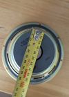
Now, onto the woofer - this seems pretty hefty (coming from a pair of tiny satellites) measuring 170mm across the face plate, 80mm across the rear magnet and about 110mm deep (was hard to measure precisely).


Speaker Enclosure
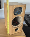
The enclosure is a solid, but cheaply made particleboard box with a faux birch veneer. The faceplate is plastic, only 3-4mm thick outside of the borders - but has reasonable stiffness. There is minimal bracing inside the enclosure, consisting of MDF wedges glued into all of the corners. The enclosure also includes a thin (maybe 10mm) piece of foam for damping, and I noted the tweeter sits inside an isolated cavity, to reduce impact from the woofers.


To the reflex bass port, this is front facing - approximately 100mm long (with the faceplate on) and appears to have some sort of divider at the internal end - the purpose of which... I'm unsure. The design includes a little rubber gasket which seals between the fixed portion of the bass port and the faceplate.


Cross-Over Details:
Now to the fun bit. After disconnecting everything, I traced out the circuit diagram by looking at component ends and figuring out which were connected.
The crossover screws into the back of the speaker and is mounted on a standoff on a custom made circuit board.
The following components were noted:
1x 3.3uF 50V electrolyte capacitor. This was swollen on one of the speakers, and I believe it led to burning out one of my tweeters.
2x 12uF 50V electrolyte capacitors.
2x Fairly large air core (or plastic core?) inductors. These appear to be custom wound, as they both use the same base - but appear to have a different number of windings.
(The long axis of the circuit board is 80mm for reference)


The swollen capacitor in the photos above was replaced with another electrolyte cap - about 1/5 the size but based on a quick google apparently cap sizes have decreased substantially in modern electronics.
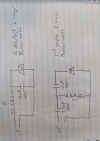
From what I can make out, and the resources I found online I'll take a stab in the dark and say it looks like this is running a Butterworth 2-nd order low pass and 3-rd order high pass?
Circuit diagram below:

As I had to replace the tweeter on one of the speakers, I also had to add a series and parallel resistor to the tweeter (I.e. resistor (about 3Ohm from memory) between the 12uF cap and the tweeter in the second diagram, then a second (I want to say 18Ohm, but i cant find my calcs!) from between the 12uF capacitor and the tweet to ground.
I can upload the modified circuit if anyone is interested. This DOES appear to have impacted the sound (and not in a good way) - but I think I've managed to correct most of it through EQ on the amplifier.
Agricultural Response Curve testing:
Please let me preface this section by saying I KNOW LITTLE ABOUT AUDIO - I'm a newbie with a cheap, calibrated USB-Mic that plugs into a smartphone so please take these readings with maybe a tablespoon of salt (a grain may not cut it!)….
Setup was to empty the room, move the speaker to the front of my coffee table on foam to try and eliminate some of the early reflection. Readings taken with a smartphone and calibrated Dayton IMM-6c on a boom stand. (Note my kids and they couch they are moving were out of the way when I did the readings

First reading: Was mic setup 550mm from the speaker - then testing in front of, and horizontally offset 200, 400 then 600 (So off axis(?) 20, 36 and 48 degrees):
I do have psychoacoustic smoothing on here - in an attempt to show the off-axis performance a bit clearer. Seems unusual that all plots converge about 3.5Khz (Possible a reflection issue here?)
SPL 40 - 95
Top trace (light blue): On Axis;
Second trace (darker purple): ~20 degrees
Third trace (darker blue): ~ 36 degrees
Fourth trace (Magenta): ~ 48 degrees

Second chart is the on-axis speaker response - 1/12 octave smoothing applied. Same empty room setup
I did notice a vibration issue somewhere between 200-300 hz - (think its the crossover mounting board) so I'll see if correcting that makes any difference to horrible peak at that point.

Last one is reproduced from the other general frequency testing thread linked above:
Green Trace: Full Setup, boom mic at listening position, furniture in place - Audyssey EQ Off (Sub crossover 100hz)
Purple Trace: Full Setup, boom mic at listening position, furniture in pace -Audyssey EQ ON (Sub crossover 60hz as set by Audyssey)
SPL Scale 40-90 dB

Wrap Up:
So that's all I have so far. All in all, I'm quite pleased with the sound as it stands. I don't have much experience with 'good' speakers so I cant really give an objective opinion - but I'm happy with where things stand.
Next steps will be making some stands for the speakers to get them off the TV cabinet, a few more tests to better understand reflections etc and room impacts (just for fun), then I want to have a crack at room tuning.
Please let me know thoughts, whether this sort of content is useful - and any tips of tricks for improving the speakers or the sound that anyone might know.
Cheers!
Xmall
I recently picked up a pair of Sony SS-NX1's from the local tip shop - was not able to find a lot of information online - so after some encouragement on another thread, thought I would post what i know from my tinkering
Photo of the speakers and my setup below:
(Noting there are plenty of mistakes with my setup - working to correct these
I should acknowledge, that I know little about audio, so I may miss important details or get things wrong. I'll try and roll any feedback back into this main post in case others in future are looking for info. I've been getting some help with the basics on another thread: https://www.audiosciencereview.com/...cy-response-testing.56193/page-2#post-2051620 - but thought I'd start a separate thread for this info.
Background:
So I picked these up from a local tip-shop for a mortgage shattering $15 (AUD) ($9.87 USD at the time of writing) - thinking what have I got to lose.
Unfortunately 1 of the speakers had a swollen cap - which led to burn-out of one of the tweeters (See the Cross-Over section below). I replaced the capacitor - changed the tweeter with an 8 OHm (from a 6OHm) then balanced the high pass impedance with a series and parallel resistor to tune volume - and minimise impact on the cross-over point.
Probably the only important bit here, is I will have modified the response from one of the speakers - so will focus on the 'original' here for any measurements etc (unless people are interested in further details on the repair).
General system Info:
From what I have read, the these were sold in the 90's as part of an 'audiophile mini-system' - As an audio novice, I am going to assume it was targeted at Audiophiles who wanted a setup in other rooms that was... not truly awful to listen to?
Photo of the system below (Curtesy of facebook)
A manual for the system can be found here: https://www.manua.ls/sony/mhc-nx1/manual?p=7
Speaker Details:
Within the manual there was limited information on the speakers but I've snipped what was shown:
Starting with the tweeter - this is a 1" dome, though I cant comment on what type. The tweeter is fixed to the face plate and sits in an isolated cavity within the main speaker enclosure (more on that below). The speaker measures around 30mm deep by 55mm across:
Now, onto the woofer - this seems pretty hefty (coming from a pair of tiny satellites) measuring 170mm across the face plate, 80mm across the rear magnet and about 110mm deep (was hard to measure precisely).
Speaker Enclosure
The enclosure is a solid, but cheaply made particleboard box with a faux birch veneer. The faceplate is plastic, only 3-4mm thick outside of the borders - but has reasonable stiffness. There is minimal bracing inside the enclosure, consisting of MDF wedges glued into all of the corners. The enclosure also includes a thin (maybe 10mm) piece of foam for damping, and I noted the tweeter sits inside an isolated cavity, to reduce impact from the woofers.
To the reflex bass port, this is front facing - approximately 100mm long (with the faceplate on) and appears to have some sort of divider at the internal end - the purpose of which... I'm unsure. The design includes a little rubber gasket which seals between the fixed portion of the bass port and the faceplate.
Cross-Over Details:
Now to the fun bit. After disconnecting everything, I traced out the circuit diagram by looking at component ends and figuring out which were connected.
The crossover screws into the back of the speaker and is mounted on a standoff on a custom made circuit board.
The following components were noted:
1x 3.3uF 50V electrolyte capacitor. This was swollen on one of the speakers, and I believe it led to burning out one of my tweeters.
2x 12uF 50V electrolyte capacitors.
2x Fairly large air core (or plastic core?) inductors. These appear to be custom wound, as they both use the same base - but appear to have a different number of windings.
(The long axis of the circuit board is 80mm for reference)
The swollen capacitor in the photos above was replaced with another electrolyte cap - about 1/5 the size but based on a quick google apparently cap sizes have decreased substantially in modern electronics.
From what I can make out, and the resources I found online I'll take a stab in the dark and say it looks like this is running a Butterworth 2-nd order low pass and 3-rd order high pass?
Circuit diagram below:
As I had to replace the tweeter on one of the speakers, I also had to add a series and parallel resistor to the tweeter (I.e. resistor (about 3Ohm from memory) between the 12uF cap and the tweeter in the second diagram, then a second (I want to say 18Ohm, but i cant find my calcs!) from between the 12uF capacitor and the tweet to ground.
I can upload the modified circuit if anyone is interested. This DOES appear to have impacted the sound (and not in a good way) - but I think I've managed to correct most of it through EQ on the amplifier.
Agricultural Response Curve testing:
Please let me preface this section by saying I KNOW LITTLE ABOUT AUDIO - I'm a newbie with a cheap, calibrated USB-Mic that plugs into a smartphone so please take these readings with maybe a tablespoon of salt (a grain may not cut it!)….
Setup was to empty the room, move the speaker to the front of my coffee table on foam to try and eliminate some of the early reflection. Readings taken with a smartphone and calibrated Dayton IMM-6c on a boom stand. (Note my kids and they couch they are moving were out of the way when I did the readings
First reading: Was mic setup 550mm from the speaker - then testing in front of, and horizontally offset 200, 400 then 600 (So off axis(?) 20, 36 and 48 degrees):
I do have psychoacoustic smoothing on here - in an attempt to show the off-axis performance a bit clearer. Seems unusual that all plots converge about 3.5Khz (Possible a reflection issue here?)
SPL 40 - 95
Top trace (light blue): On Axis;
Second trace (darker purple): ~20 degrees
Third trace (darker blue): ~ 36 degrees
Fourth trace (Magenta): ~ 48 degrees
Second chart is the on-axis speaker response - 1/12 octave smoothing applied. Same empty room setup
I did notice a vibration issue somewhere between 200-300 hz - (think its the crossover mounting board) so I'll see if correcting that makes any difference to horrible peak at that point.
Last one is reproduced from the other general frequency testing thread linked above:
Green Trace: Full Setup, boom mic at listening position, furniture in place - Audyssey EQ Off (Sub crossover 100hz)
Purple Trace: Full Setup, boom mic at listening position, furniture in pace -Audyssey EQ ON (Sub crossover 60hz as set by Audyssey)
SPL Scale 40-90 dB
Wrap Up:
So that's all I have so far. All in all, I'm quite pleased with the sound as it stands. I don't have much experience with 'good' speakers so I cant really give an objective opinion - but I'm happy with where things stand.
Next steps will be making some stands for the speakers to get them off the TV cabinet, a few more tests to better understand reflections etc and room impacts (just for fun), then I want to have a crack at room tuning.
Please let me know thoughts, whether this sort of content is useful - and any tips of tricks for improving the speakers or the sound that anyone might know.
Cheers!
Xmall
Attachments
Last edited:


