I'm actually an electrical engineer. I spent a short amount of time studying the Infineon reference design the AO200 is based on. The outputs caps are the source of the noise for sure, but I didn't get much further into it.
I agree, these filtering caps look a lot like class 2 dielectric MLCCs which are known to be microphonic. They are also known to not be very linear. The selection surprised me since they'd be outside of the feedback loop and thus this distortion of LC components wont even be suppressed by feedback.
Upon further reading I saw this on page 12/86 in the datasheet
"Notably, with the multi-level modulation of the MA12070, there is no tradeoff between idle power loss and inductor cost/size, which is due to the absence of inductor ripple current under idle conditions in all configurations. Due to the high filter cutoff frequency, non-linearities of LC components have less impact on audio performance than with a conventional amplifier. Therefore, theMA12070 can operate with inexpensive iron-powder cored inductors and ceramic (X7R) filter capacitors with no significant audio performance penalty."
So they found a way of pushing those non-linearities in cheaper components further out of the audible band, which is nice, but it adds the problem of microphonics. But shouldn't those vibrations in the MLCCs be way outside of the audible band, how come you can hear them ? Feedback loop instability ? Limit cycles due to non-linearities ?
One possible, somewhat cheap, solution could be to use soft terminated MLCC with X7R characteristics. These add a conductive resin on the solder pads that is a lot softer than the ceramic materials and acts as a mechanical decoupler for vibrations. From my experience you could get something like a 10-20dB dampening of those capacitors compared to the regular ones.
The other option is to change over to either class 1 dielectric MLCC (C0G, NP0 types) or film caps. Those will probably be bigger in size though and therefore have higher series inductance.
I'm too trying to decide between a DA9 and a AO200, and it seems that they both have their respective design problems. The screws to clamp down the chip to the cooling pads in the DA9 are scaringly close to the, very sensitive, ceramic caps. I can easily see how you'd get microcracks in those capacitors when you are tightening the screws. On the other hand the AO200 cooling solution also seem a bit....meh.
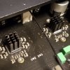
Edit: On closer inspection it seems that what I thought were the filtering caps are actually flying capacitors for creating an intermediate rail with their fancy modulation scheme. Datasheet recommends 2x10µF 0805, so those are 4 of the 6 larger capacitors on the side of the amp IC. Those should be humming along at the switching frequency, which is what, 600kHz ?, so way outside audible spectra. I haven't really fully understood the modulation so I guess there might be some lower frequency "superimposed" on that though. The actual filtering caps are the film caps close to the binding posts. I'd suspect some beads on the back side then. That'd leave the decoupling capacitors as prime suspects of potential noise sources. From what it looks like they could easily be swapped out for some ultra low ESR polymer tantalum capacitors for a bit of extra umphf and quietness.
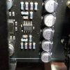
Noise from ceramic caps like these are unavoidable as they expand and contract with varying voltage, causing the whole board to participate in the music.

")