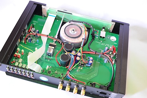
I recently reviewed the Rega IO amplifier. It did not perform well and got very hot. Members asked for a teardown and with kind permission of the owner, here it is: (click on image for 2X size):

Two ultra long screws is all that holds the thing together going from the back to front. Keeps labor costs low in assembly. Pray for me that they have a channel they go into so putting it back together won't be a nightmare!
AC mains from IEC terminal on top right is routed to the front panel for the power switch and then back. I would have liked to see some routed areas along that path to keep chances of arcing to a minimum.
On top you see the power supply rectification and filtering. That is fed with a toroidal transformer rated at ± 22 volts at 2.7 amps (from memory). The filter caps are secondary brand "Samhwa." We could forgive that but not the rating of just 85 degrees C as opposed to 105C. Considering how hot that side of the case was in my testing, I don't know how long these caps will last. Then again, with such height restriction, they probably did not have the option of getting a higher rated cap which would likely be larger/taller.
The main question was around source of the heat. I measured the left and right sides as being the hottest in the review:

As far as I can tell, there is nothing mounted on them. The power stage is those 5-pin transistors mounted to the bottom of the case. Could it radiate this much heat to the sides? Or are the rectifier diodes adding to it?
I made a light attempt at taking the tiny heatsink off them but they are screwed on tight. I did not want to force anything given how close to the edge this unit is on the thermal side. The transistors are quite large though so likely rated for good power handling.
I was surprised to see a number of through-hole transistors in there. Wonder what was special about them that they went through the expense of using them instead of surface mount ones.
I really liked the captive ring spade connectors for speaker terminals. They were screwed on tight with what seemed to be molded channel to hold them in their orientation. This should keep them from coming lose.
Overall, hard to find faults with the design of the unit given the heavy constraints of a compact unit like this using inefficient class AB amplification topology.
------------
As always, questions, comments, recommendations, etc. are welcome.
Any donations are much appreciated using: https://www.audiosciencereview.com/forum/index.php?threads/how-to-support-audio-science-review.8150/
Two ultra long screws is all that holds the thing together going from the back to front. Keeps labor costs low in assembly. Pray for me that they have a channel they go into so putting it back together won't be a nightmare!
AC mains from IEC terminal on top right is routed to the front panel for the power switch and then back. I would have liked to see some routed areas along that path to keep chances of arcing to a minimum.
On top you see the power supply rectification and filtering. That is fed with a toroidal transformer rated at ± 22 volts at 2.7 amps (from memory). The filter caps are secondary brand "Samhwa." We could forgive that but not the rating of just 85 degrees C as opposed to 105C. Considering how hot that side of the case was in my testing, I don't know how long these caps will last. Then again, with such height restriction, they probably did not have the option of getting a higher rated cap which would likely be larger/taller.
The main question was around source of the heat. I measured the left and right sides as being the hottest in the review:
As far as I can tell, there is nothing mounted on them. The power stage is those 5-pin transistors mounted to the bottom of the case. Could it radiate this much heat to the sides? Or are the rectifier diodes adding to it?
I made a light attempt at taking the tiny heatsink off them but they are screwed on tight. I did not want to force anything given how close to the edge this unit is on the thermal side. The transistors are quite large though so likely rated for good power handling.
I was surprised to see a number of through-hole transistors in there. Wonder what was special about them that they went through the expense of using them instead of surface mount ones.
I really liked the captive ring spade connectors for speaker terminals. They were screwed on tight with what seemed to be molded channel to hold them in their orientation. This should keep them from coming lose.
Overall, hard to find faults with the design of the unit given the heavy constraints of a compact unit like this using inefficient class AB amplification topology.
------------
As always, questions, comments, recommendations, etc. are welcome.
Any donations are much appreciated using: https://www.audiosciencereview.com/forum/index.php?threads/how-to-support-audio-science-review.8150/

