Interesting if the device was opened up as a tear down to see what makes that LED flash

http://collinsaudio.com/Prosound_Workshop/Noise_Harvester.pdf
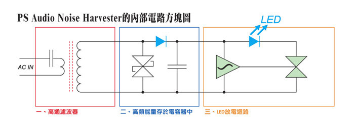
The red block on the left is a toroid which doesn't do much for mains frequencies. For that one would need a different
core.
The capacitor also works as a high-pass ensuring mains frequencies as well as the more powerful harmonics don't make it in the electronics behind it. It will 'start' to become a lower resistance the higher the frequency becomes. At 500Hz it still doesn't 'do much' but at 10kHz to 10MHz it will.
The blue block is a
transzorb that 'clamps' (basically shorts) voltages that exceed the voltage threshold and stops shorting when a lower voltage is reached.
This basically does the 'work'. It is a symmetrical device so it 'clamps' positive and negative going voltages.
So any 'peak voltage' above 500Hz and a specific voltage will provide a 'low resistance' to those signals.
Of course the resistance of that path differs per frequency as the capacitor and transformer also have a resistance.
It thus won't remove the complete 'noise' but will lower it. That is why paralleling the devices 'works'
Use 2 and the load will be double that. To double the 'load' to the noise again you need 4 and again you need 8...
However, the energy there (above 500Hz in 'differential mode') is very low and may not even exceed the clamping voltage of the transzorb.
To still 'show' there is energy there (that really isn't clamped at all) the orange block is needed.
The orange 'block' is the so called 'harvester' part. A harvester kind of 'collects' energy. The
diode (probably a Schottky diode) in the blue block will charge a small capacitor with the 'energy' (very low in power) and thus those small amounts of 'energy' are 'added' to the capacitor until a voltage threshold is reached and that capacitor will be discharged through a very efficient low power blue LED. The more energy it will receive in a specific over time the faster it will blink. A blue LED will light up on less than 1mA and as the blink is short the overall energy needed to make it blink is VERY low. After the LED 'flashed' the 'harvesting' process repeats again. The block schematic shows 1 diode but it looks like there are 2 of them that form a full wave bridge rectifier.
That harvested 'energy' is what makes the light flash. It is an indicator not the actual part that removes or dissipates the heavy lifting energy.
The 'heavy duty' parts (that raise the temp inside) is the transformer (which also dissipates the mains harmonics a bit) and the transzorb. The LED is merely an 'indicator'.
HF crap is not differential mode (in general) but common mode. The harvester does nothing for that as it only can do something differential mode.
Differential mode = a voltage between Live and Neutral.
Common mode = a voltage between the Live (and Neutral) and ground. A common mode signal thus will have the same amplitude on both the L and N wire and thus is not differential (no signal between L and N).

