OP
JP
Major Contributor
- Thread Starter
- #201
Not looking at its peak - more at the curve profile and where it rises to its peak - the needle will reach it's minimum tracking ability at the resonance frequency of the cantilever, where the resonance itself will interfere with consistent mechanical contact with the groove, resulting in rising distortion - and after the resonance the distortion level drops off....
the cantilever resonance of course has its own multiple harmonics, so if you have the ability to measure high enough in frequency, and the needle profile is fine enough to track at very high frequencies, you should see the harmonics of the resonance both in the F/R and in the distortion.
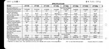
And yet there’s nothing remarkable in the distortion profile of the plot compared to others, even those with lower ETM.