• WANTED: Happy members who like to discuss audio and other topics related to our interest. Desire to learn and share knowledge of science required. There are many reviews of audio hardware and expert members to help answer your questions. Click here to have your audio equipment measured for free!

Inductors as an Audio Enhancer

OP
Newman

Newman

Major Contributor
Joined
Jan 6, 2017
Messages
3,530
Likes
4,370
Thanks guys, I am hearing from you a lot about the negatives of inductors, which is all well and fine.

But the thread question is, what is the mechanism, even if it is incorrect, that these guys are saying makes inductors a good choice? What possible line of logic are they buying into?
 

Holmz

Major Contributor
Joined
Oct 3, 2021
Messages
2,020
Likes
1,242
Location
Australia
Thanks guys, I am hearing from you a lot about the negatives of inductors, which is all well and fine.

But the thread question is, what is the mechanism, even if it is incorrect, that these guys are saying makes inductors a good choice? What possible line of logic are they buying into?

Could possibly be buying into the hysterysis of the dielectric, but core materials also have a hystery.
One thing is possibly true though… if the output imdekance is lower, then it would make a better version of a passive preamp for all amps with a finite input impedance.
 

solderdude

Grand Contributor
Joined
Jul 21, 2018
Messages
16,054
Likes
36,443
Location
The Neitherlands
Thanks guys, I am hearing from you a lot about the negatives of inductors, which is all well and fine.

But the thread question is, what is the mechanism, even if it is incorrect, that these guys are saying makes inductors a good choice? What possible line of logic are they buying into?

It all has to do with capacitor size. The VU product. A high voltage electrolytic capacitor can't have a substantial capacitance.
A 2200uF/50V capacitor has the same size as 220uF/400V capacitor.
Currents drawn (both peak and continuous) differ of course.

The ripple on a tube amp power supply is bigger than that on a low voltage (higher capacitance) power supply in an absolute sense. Relatively they are about the same.
Often tube amp circuits have a poor PSRR so any ripple can make it into the audio path. For this resistors are often used to create a low-pass filter.
This is only 6dB/oct. You can double that to 12dB/oct. and get the cutoff point lower using an inductor instead of a resistor so a smaller ripple.

Whether that is audible or not is another matter. It would have to be tested blind (instead of knowing and believing an inductor contains magic)

So in a DC powerline adding an inductor lowers ripple and a dip on voltage of the capacitors after a large current was drawn can be replenished a bit faster than when a resistor was to be used that had the same ripple.

Of course one can also use regulator tubes but these require a higher rectified DC (to compensate for the voltage drop) and eat up energy (heat) and limit the max available current.

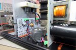
He has in mind an RIAA circuit that “is entirely inductor based”… not sure if that means no capacitors, or also minimal resistors. He showed me a test inductor that he is winding with what looks like a ferrite drum sleeve.
He probably wants to replace the RIAA filter with inductors. That can be done of course but will require excellent shielding of the inductors in order for the circuit not to pick up hum from nearby power transformers etc.

Probably just a guy who wants to do things different for the sake of being different or a curious belief that somehow this is better or contains more 'magic'.
The latter will be confirmed as the listener will know what's in the circuit.

Time to ignore them and when they built it have them do a blind test.
 
Last edited:

antcollinet

Master Contributor
Forum Donor
Joined
Sep 4, 2021
Messages
7,745
Likes
13,072
Location
UK/Cheshire
Run a current thru an inductor, disconnect, how long will the current run? Which stores the energy better (at room temp)?
Thats an incorrect comparison. (if by disconnecting of an inductor you mean open circuiting it)

The equivalent to disconnecting a capacitor is short circuiting an inductor. The current will continue to flow (be stored), just as a capacitor will store the voltage. The current will decay due to coil resistance just as voltage in the cap will decay due to leakage resistance between the plates.

Disconnecting an inductor is the equivalent to short circuiting a capcitor. Both wil release the energy quickly - the capacitor as a massive pulse of current, the inductor as a massive pulse of voltage (often enough to cause a spark accross the switch contacts of the switch you have disconnected it with, or to kill the transistor if you've used one as the switch and not included a snubber circuit.)
 
Last edited:

solderdude

Grand Contributor
Joined
Jul 21, 2018
Messages
16,054
Likes
36,443
Location
The Neitherlands
To elaborate a bit more..

Its also the reason why a relay that is driven by a transistor always has a diode across it in 'reverse'.
That stored current can't flow when one disconnects the relay (transistor open circuit).
In that case the current wants/needs to flow but there is no 'path' for it. current x very high resistance = very high voltage.
That voltage peak will exceed the CE voltage of the transistor and blow it.
The (reverse) diode will let the current flow as the current will be in the opposite direction as the current in on position.
During that time the relay will still be having a magnetic field so will fall off a bit later than expected. One can make that a little quicker by adding a zener (in anti-series) with the diode that has a breakdown voltage a little lower than the transistor. With this trick the current will dissipate a tiny bit faster. In most cases that would be pointless.

It also is the same reason sparks will fly when pulling a mains plug. One breaks the circuit. Current wants to flow (inductance of transformer) but can't as there is no way for it so the voltage spikes and makes the spark.

That is why mains switches often have a capacitor or VDR across them. That cap will conduct that current and prevent a high voltage peak and thus there will be no spark in the switch prolonging its life.
 

Waxx

Major Contributor
Joined
Dec 12, 2021
Messages
1,984
Likes
7,884
Location
Wodecq, Hainaut, Belgium
The story that inductors have a good sound come from inductor based eq's, where a lot of unshielded small inductors are sitting close to each other and where the magnetic field interacts and give an euphonic distortion. This is used in some older eq types used in studio's as effect, but is unwanted in hifi in the strict sense of the word (like seen here) as it is distortion. Saturation of those small inductors also plays a role in that colouration. I'm not an EE that can explain this in detail, but this has been discussed in detail on diyaudio.com with all the math included years ago.
 

MaxwellsEq

Major Contributor
Joined
Aug 18, 2020
Messages
1,752
Likes
2,646
Thanks guys, I am hearing from you a lot about the negatives of inductors, which is all well and fine.

But the thread question is, what is the mechanism, even if it is incorrect, that these guys are saying makes inductors a good choice? What possible line of logic are they buying into?
In terms of the "volume control", an autoformer or autotransformer has an advantage over a "passive" (attenuation only), preamplifier using a simple potentiometer, because of how it can be made to deal with the impedance impacts sometimes experienced with the latter. Personally I prefer to have an active preamplifier with buffers an positive gain if needed.


Cbdb2

Major Contributor
Joined
Sep 8, 2019
Messages
1,555
Likes
1,534
Location
Vancouver
Thats an incorrect comparison. (if by disconnecting of an inductor you mean open circuiting it)

The equivalent to disconnecting a capacitor is short circuiting an inductor. The current will continue to flow (be stored), just as a capacitor will store the voltage. The current will decay due to coil resistance just as voltage in the cap will decay due to leakage resistance between the plates.

Disconnecting an inductor is the equivalent to short circuiting a capcitor. Both wil release the energy quickly - the capacitor as a massive pulse of current, the inductor as a massive pulse of voltage (often enough to cause a spark accross the switch contacts of the switch you have disconnected it with, or to kill the transistor if you've used one as the switch and not included a snubber circuit.)
Sorry I was being lazy and I need to remember theres people reading this that dont have much electronics training.
When "disconnecting " the inductor I mean removing the current source while leaving a loop (you could use a transformer). You would end up with a short across the inductor (eqauivalent to an open cap). If it was a perfect inductor the current flowing before the disconnect would continue flowing forever, and the mag field would be constant. Equivalent to the perfect cap voltage remaining forever after disconnect, and the E-field remaining constant.
What I was getting at was that the wire resistance in an inductor makes it lossier than the leakage resistance in a cap.
Disconnecting an inductor loop with current flowing, as you said will develop a large voltage, the equivalent with a charged cap is shorting it which develops a large current.

Basically when switching between caps and inductors you swap voltage for current, invert resistances (open circuits for shorts), and swap hi freqs for low freqs. Similar to converting voltage sources to current sources.
 

Cbdb2

Major Contributor
Joined
Sep 8, 2019
Messages
1,555
Likes
1,534
Location
Vancouver
It all has to do with capacitor size. The VU product. A high voltage electrolytic capacitor can't have a substantial capacitance.
A 2200uF/50V capacitor has the same size as 220uF/400V capacitor.
Currents drawn (both peak and continuous) differ of course.

The ripple on a tube amp power supply is bigger than that on a low voltage (higher capacitance) power supply in an absolute sense. Relatively they are about the same.
Often tube amp circuits have a poor PSRR so any ripple can make it into the audio path. For this resistors are often used to create a low-pass filter.
This is only 6dB/oct. You can double that to 12dB/oct. and get the cutoff point lower using an inductor instead of a resistor so a smaller ripple.
But the higher voltage cap stores over 6 times the energy in the same volume. E=CV*2
 

fpitas

Master Contributor
Forum Donor
Joined
Jul 7, 2022
Messages
9,885
Likes
14,212
Location
Northern Virginia, USA
Gotta love cargo cult electronics :facepalm:
 

Sokel

Master Contributor
Joined
Sep 8, 2021
Messages
6,130
Likes
6,206
Gotta love cargo cult electronics :facepalm:
It's probably an attempt to copy or understand Halcro's performance judging only by the visuals.
Thing is that this thing is made by someone who has nothing to do with audio,I suspect he made it just to saw people that it can be done.
 

fpitas

Master Contributor
Forum Donor
Joined
Jul 7, 2022
Messages
9,885
Likes
14,212
Location
Northern Virginia, USA
It's probably an attempt to copy or understand Halcro's performance judging only by the visuals.
Thing is that this thing is made by someone who has nothing to do with audio,I suspect he made it just to saw people that it can be done.
Exactly. Don't bother to understand the first thing about it.
 

Cbdb2

Major Contributor
Joined
Sep 8, 2019
Messages
1,555
Likes
1,534
Location
Vancouver
To elaborate a bit more..

Its also the reason why a relay that is driven by a transistor always has a diode across it in 'reverse'.
That stored current can't flow when one disconnects the relay (transistor open circuit).
In that case the current wants/needs to flow but there is no 'path' for it. current x very high resistance = very high voltage.
That voltage peak will exceed the CE voltage of the transistor and blow it.
The (reverse) diode will let the current flow as the current will be in the opposite direction as the current in on position.
During that time the relay will still be having a magnetic field so will fall off a bit later than expected. One can make that a little quicker by adding a zener (in anti-series) with the diode that has a breakdown voltage a little lower than the transistor. With this trick the current will dissipate a tiny bit faster. In most cases that would be pointless.

It also is the same reason sparks will fly when pulling a mains plug. One breaks the circuit. Current wants to flow (inductance of transformer) but can't as there is no way for it so the voltage spikes and makes the spark.

That is why mains switches often have a capacitor or VDR across them. That cap will conduct that current and prevent a high voltage peak and thus there will be no spark in the switch prolonging its life.
My first EE gig was designing flare stack ignition systems. Basically giant spark plugs. We had a battery operated one that used a pulsing circuit and a car ignition coil. The spark would jump 4 inches (over 60kv). It took a while to figure out how to protect the drive circuit transistor (which were crt flyback and could take 1000v), ended up needing a cap as well as the diode.
 

solderdude

Grand Contributor
Joined
Jul 21, 2018
Messages
16,054
Likes
36,443
Location
The Neitherlands
TV's of old all had those HV caps in conjuction with diodes in the flyback circuit.
I still have a bunch of them in a box.
About 11nF and a few kV rated I vaguely remember.
 

fpitas

Master Contributor
Forum Donor
Joined
Jul 7, 2022
Messages
9,885
Likes
14,212
Location
Northern Virginia, USA
TV's of old all had those HV caps in conjuction with diodes in the flyback circuit.
I still have a bunch of them in a box.
About 11nF and a few kV rated I vaguely remember.
The later big screen TVs made it up to 25kV or so, although the capacitor was the final anode metallization inside the CRT.
 

fpitas

Master Contributor
Forum Donor
Joined
Jul 7, 2022
Messages
9,885
Likes
14,212
Location
Northern Virginia, USA
Jealous much???

View attachment 331270

(Halcro)

If he also achieves such performance I bow to him!
At a guess, those inductors are simply part of the output stabilization network, generally a uH or two. They protect the output transistors from the unknown reactance from cables, speakers etc.
 

Sokel

Master Contributor
Joined
Sep 8, 2021
Messages
6,130
Likes
6,206
At a guess, those inductors are simply part of the output stabilization network, generally a uH or two. They protect the output transistors from the unknown reactance from cables, speakers etc.
There's lots of history behind it,specially his insistence about certain metal alloys (he makes the best metal detectors in the world,is a little like a mad scientist) and some of the things he has included I don't even know how to use,specially the inputs:

Power


  • Power output into 4 ohms resistive > 500 W
  • Power output into 8 ohms resistive > 280 W

(Measured at 1kHz)


Distortion (Footnote 1)


  • At full power output, all harmonic distortion orders:
  • THD <-120 dB (<300 parts per billion) up to 20 kHz (100 kHz B.W.) at 450 W into 4 ohms.
  • THD @ 1 kHz <-134 dB (<200 parts per billion).
  • For sum of 19 and 20 kHz tones, each delivering 112.5 W into 4 ohms = peak power 450W, resulting intermodulation products each <-120 dB relative to output.
  • SMPTE-IM intermodulation products each
    <-120 dB relative to output.

Inputs


There are four input modes:


  • an unbalanced voltage mode input with an impedance of 22 kOhms
  • a balanced voltage mode input with an impedance of 22 kOhms + 22 kOhms
  • a current-mode input with a 60 Ohm input impedance (infinite impedance current source)
  • a minimal path voltage mode with an input impedance of 660 Ohms

The voltage gain of the balanced and unbalanced inputs is 30 V/V and for the minimal path mode is 15 V/V. The gain of the current mode is 9 V/mA


Noise


The equivalent input noise at the input is 5 nV/sqrt(Hz) for the voltage modes and 6 pA/sqrt(Hz) for the current mode.


Frequency Response


  • 3Hz – 215kHz: -3db
  • 7Hz – 90kHz: -1dB

(Measured at 1W output)


Slew rate limit


Maximum slew rate for both small signal and maximum output voltage is 100V/μs (which is equivalent to a maximum output voltage at approximately 250 kHz).


Power supply​


  • active power factor correction minimizes mains current harmonic distortion
  • operates at all voltages from 85 to 270 V r.m.s. 45-65 Hz, without any internal or external switches
  • less than 100 parts per million mains hum and ripple on the amplifier power rails
  • conforms with PFC and EU emission standards set for 2002

That's a strange looking trafo there:

1701640484642.jpeg
 

fpitas

Master Contributor
Forum Donor
Joined
Jul 7, 2022
Messages
9,885
Likes
14,212
Location
Northern Virginia, USA

fpitas

Master Contributor
Forum Donor
Joined
Jul 7, 2022
Messages
9,885
Likes
14,212
Location
Northern Virginia, USA
specially the inputs
I've never seen current mode used for audio. I designed a special vibration sensor system for the Navy that used it, but they weren't real worried about high-fidelity so much as minimal noise pickup.
 

Sokel

Master Contributor
Joined
Sep 8, 2021
Messages
6,130
Likes
6,206
I've never seen current mode used for audio. I designed a special vibration sensor system for the Navy that used it, but they weren't real worried about high-fidelity so much as minimal noise pickup.
I wouldn't even know what to plug in it! :facepalm:

Are there any benefits or is just some of it's mad stuff?

(seriously now,he must be of the first using a 6-layer PCB in audio back then,thinking outside the box has it's use probably)
 
Top Bottom