
Robocop
Member
Some may find this an interesting read. At the cutting edge of measurement. Robert
 audioxpress.com
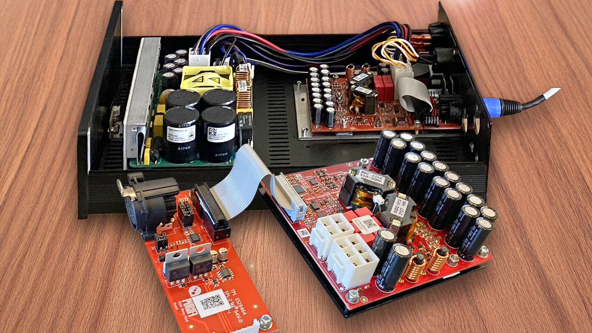
Fresh From the Bench: Purifi 1ET9040BA Balanced Class-D Amplifier Module
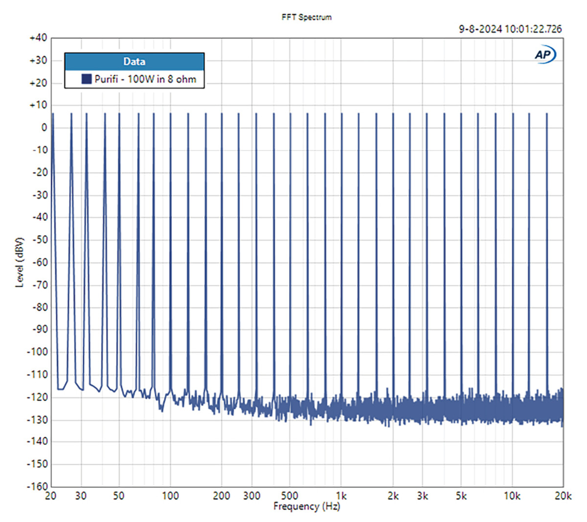
The Purifi 1ET9040BA balanced Class-D amplifier module, a Bridge-tied-load (BTL) output stage, is the second product in the company's Eigentakt range. Following a conversation with members of Purifi about the amplifier's audio performance being hard to measure even with the best available test...
 \I now see what you both mean, "Purify"