• WANTED: Happy members who like to discuss audio and other topics related to our interest. Desire to learn and share knowledge of science required. There are many reviews of audio hardware and expert members to help answer your questions. Click here to have your audio equipment measured for free!

Floating-Point ADC System

In fact member sm5 (no longer active) posted some Merging Anubis tests. Anubis also advertised a similar ADC technology.
The quote box in my post contains the original text content, but unfortunately the graphs are gone, and sm5 modified and removed all the the posted reports. You can see my reply has a comment about the Anubis too.


The quote box in this post also includes another (removed) comment of the Anubis from sm5:


Why? I can't be sure, but two things. Firstly, member jerryfreak later posted some results of other ADCs which wiped the floor of the Anubis.

Secondly, Cosmos ADC also showed up later on which also wiped the floor of the Anubis. I suspect leaving the test results of the Anubis here can potentially hurt the selling price in 2nd hand market, as a precaution, the reports are removed.

That said, from what I have seen in the Anubis reports, the results are indeed much better than Zoom F6, yet still far away from Cosmos ADC and some of the products that jerryfreak posted.
 
It would never work well this way. The multiplexer would generate audible glitches.
If each attenuation/gain path has its own ADC it could work.
The dsp would need to merge the synchronous ADC channels.
Having all these channels available in parallel also makes calibration more easy.
With a lot of trimming (of gains and offsets and switch timing) and enough oversampling/filtering the real-time switching for a single channel might even work with low distortion and low enough glitches but then you'd still have noise-floor modulation and other things resulting from the step change of gains, so yes, for audio this is not feasible concept.

The parallel approach also has challenges to deal with (some detailed here) but at least the glitching and sudden noise floor change etc is removed/mitigated by the gradual crossfade rather than instantaneous switching of paths.
 
Last edited:
What is it that Sound Devices do in their products that claim a super wide dynamic range, and that you can record without every worrying about clipping being possible? I'd thought it was what MC_RME is describing, but then it just didn't do well in testing by Amir here.
Where did Amir test a Sounddevices device? Maybe I missed that...

Reading here and the other thread there seems to be some missing piece to understand the concept. The 'quality' of a multistage ADC converter is not better than a single ADC. Only the SNR is better. Think about a 0 dBFS 1 kHz FFT with a SINAD of 100 dB for one converter. Using three of them would not change that SINAD, it might even get a bit worse due to overlap issues (check the THD+N values of SoundDevices: 0.005% = -86 dB). But the multi-staged ADC technology gives this SINAD not only at one fixed level, but over a big range. Without any sound you operate at a very low input level, which compared to the maximum possible input level results in a very impressive Signal to Noise Ratio (and Dynamic Range, measured at -60 dBFS). But as soon as the top level of the first ADC is reached the noise floor and harmonics will move up, together with the fundamental....the FFT picture literally moves as whole, up and down.

There are pics in the web that explain this better than I can do. The first dual stage (studio audio) converter I have seen was from Yamaha in the 80's (AFAIR). Later Stagetec became famous for their multi-ADC system called TrueMatch, which plays in a whole different league. This is not for 'field recording' but studio and live recording, and much more expensive.
 
Without any sound you operate at a very low input level, which compared to the maximum possible input level results in a very impressive Signal to Noise Ratio (and Dynamic Range, measured at -60 dBFS). But as soon as the top level of the first ADC is reached the noise floor and harmonics will move up, together with the fundamental....the FFT picture literally moves as whole, up and down.
Yes, which is why I propose a different/additional noise measurement for such devices (to @amirm or anyone else).
A modified Dynamic Range test with a full scale test signal, instead of -60dB. Or a bit less than full scale, if it helps to lower distortion, as long as it ends in the "top ADC" range -- it should be evident when looking at the FFT.
 
Let me borrow a graph from @Julian Krause for illustration.
uac232-mic-sweptimd.png

That big "kink" there in the middle is where the ADC switching occurs (it's a dual ADC affair).

You can also buy ADCs with analog range extension / gain switching, e.g. ES9826.

The first dual stage (studio audio) converter I have seen was from Yamaha in the 80's (AFAIR). Later Stagetec became famous for their multi-ADC system called TrueMatch, which plays in a whole different league. This is not for 'field recording' but studio and live recording, and much more expensive.
I'll have to research these. As one of the resident young whippersnappers (relatively speaking), I would have been far too busy with learning my ABCs when that Yamaha came out. ;) (I wasn't even aware of them making ADCs.)

As far as Stagetec TrueMatch is concerned, that appears to be going back to 1996. This would predate it then:

Studio Sound, March 1995
DG 4D goes to third generation

The Deutsche Grammophon Recording Centre has developed a third generation upgrade of the Stage Box system central to the 4D recording chain. All recordings made by the Recording Centre since October 1994 have used the new DG AD III technology, whose convertors feature the new Crystal CS5390 delta-sigma 20-bit A-D convertor ICs to provide 23-bit digital-floating delta-sigma A-D conversion. The process employs two 20-bit convertors, one handling the input signal at unity gain and the other operated with 18dB gain. A sophisticated DSP algorithm regulates the crossfade between the two convertors, producing three bits of supplementary resolution. The DSP program was modified to allow the DSP chip to handle 20-bit convertors at its inputs and a 24-bit wordlength at its outputs. Quoted specifications include THD+n of -121dBFs with an input of 997Hz at -30dBFs and linearity errors within 1dB down to -135dBFs, together with a largely flat noise-spectrum. A further improvement is the development of the Authentic Clock Recovery system, permitting superior reconstruction of the master clock signal under real world operating conditions such as long cable runs and numerous interconnected PLLs, where phase modulation of the clock, jitter, becomes a limiting factor on overall system performance. Because Authentic Clock Recovery uses crystal PLLs driven at 512Fs, as opposed to the current 256Fs standard, A-D conversion at up to 96kHz is possible, with full oversampling capability.
Deutsche Grammophon, Germany. Tel: +49 4044 181115.
 
Last edited:
Sorry it was not Sound Devices Amir tested, but a Zoom device with a similar concept.
 
Yes, which is why I propose a different/additional noise measurement for such devices (to @amirm or anyone else).
A modified Dynamic Range test with a full scale test signal, instead of -60dB. Or a bit less than full scale, if it helps to lower distortion, as long as it ends in the "top ADC" range -- it should be evident when looking at the FFT.
What you propose is THD+N at full level. Is already done.
 
I don't know what it is good for to remove the harmonics here. The number resulting would be of no practical meaning as in reality they will be there.
 
Noise and distortion might not be equally audible at the same level (sometimes there's a big difference). And even if audible, harmonic distortion is not always as undesirable as noise. So it's good to measure them separately.

And it could also make sense to use a different test tone here (like 15kHz instead of 1kHz) to more easily isolate the noise floor.

Modern (FFT-based) measurement software already can do this with 0dBFS 1kHz or 15kHz or other frequency signal. Noise can be computed separately from distortion, and this is routinely done by Multitone, REW, and I assume, by APx software. In fact, this can even be done with multitone test signals with not too much more trouble.
 
You'd think I would know better by now...

This was just an example to illustrate how floating-point ADCs might work and not a treatise on how to design such a converter. It is a very simplified form to show how floating-point operation might provide performance gains. It is not meant to be (and is not) an architecture or implementation guide. For audio and at this time I would use multiple amps and ADCs, probably delta-sigma as mentioned in the other thread, to take advantage of modern processing and DSP.

The scheme I showed was used many years ago in an RF system where there was other gain switching involved so some "dead time" was expected. And the ADC operated at several GS/s, burning too much power to use multiple ADCs in parallel (especially in flight hardware), though there were already two of them (I/Q system).

I'll leave the rest to the experts. A number of good points made, but this was only a very basic tutorial targeting non-engineers, not a detailed design guide.
 
Don't worry, it's fine.

Anyway...

Audio​


  • audio connections are made entirely via the digital Nexus routing system
  • sampling rates: 32 kHz, 44.1 kHz, 48 kHz (44.056 kHz and 47.95 kHz when synchronized externally)
  • analog full-scale level: 0 dB FS = 0...22 dBu, adjustable for the overall system
  • line inputs: 22 bit TrueMatch-AD, dynamic range 126 dB (A) typically
  • microphone inputs: 28 bit TrueMatch-AD, dynamic range 152.5 dB (A) typically
  • line outputs: 24 bit DA, dynamic range 127 dB (A) typically
All that in 1997. Impressive. As I imagine was the price tag for an advanced mixing console like that. Customers seem to have been mainly theatres and public broadcasters. If you "just" needed an ADC and DAC, there would still have been the budget option, the Pacific Microsonics Model Two (out in '96 if memory serves). Or waiting for the Prism Sound DREAM AD-2 ('98).
 
Last edited:
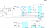
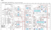
In addition to the normal signal path ADC, this recorder had a -20dB input ADC operating at the same time. However, it is 24 bit. I think it was released about 20 years ago.

I think Prism AD-2 is still fine, but can PMI model 1 or 2 be repaired or maintained? That being said, there is no substitute, especially when it comes to the AD section.
 

Attachments

  • pcmd1_block_adc.png
    pcmd1_block_adc.png
    225.5 KB · Views: 98
  • pcmd1_schematic_adc.png
    pcmd1_schematic_adc.png
    444.7 KB · Views: 97
Noise and distortion might not be equally audible at the same level
Noise is not audible at all. Not in the presence of a sine at least 80 dB higher in level (fully masked). And without sine we are back to SNR.
 
Noise is not audible at all. Not in the presence of a sine at least 80 dB higher in level (fully masked).
It depends. Some strong low end rumble might not mask the noise, after that rumble is removed in post and the recording is amplified/compressed. Same goes for ultrasonic or other unwanted content that gets filtered out later.
These are sort of worst case scenarios, but it's nice to have the data anyway.
 
I measured the THD, THD+N, Noise Level vs Calibrated Input RMS of the XLR mic input of Zoom UAC-232 simultaneously using a 1kHz sine wave. Its amplitude was stepped up from 5μVrms to 1.66Vrms (or 2.35Vp, i.e. 0 dBFS according my calibration, with the digital gain set to 0dB) in 300 increments. The following are the results.

NoiseLevelvsAmpXLRwithout48V300pt.png
Noise Level (20Hz~20kHz) vs Calibrated Input RMS
THDvsAmpXLRwithout48V300pt.png

THD vs Calibrated Input RMS

THDNvsAmpXLRwithout48V300pt.png

THD+N vs Calibrated Input RMS

The results above indicate that the switching between the two ADCs occurs at 0.03Vrms. The noise level of the high-gain ADC (when the input RMS<0.03Vrms) was slightly overestimated in the first graph above, because the signal generator I used has a little bit higher noise level than the device under test.

The following two pictures show the noise level with and without A weighting when the XLR input (+) and (-) are shorted to ground. Obviously this noise level was from the high-gain ADC. It is about 2.5 dB lower than the noise level measured with a 1kHz signal from the signal generator. In these two pictures, the voltages were uncalibrated, but the reference of 0 dBFS is always the sample value of 1, which was also found to be the maximum value beyond which clipping will happen when the digital gain is set to 0dB. Therefore, the dynamic range here is about 134.3dB or 136.4dBA.

NoiseLevelXLRwith48V.png

Noise Level (No weighting)

NoiseLevelXLRwith48VandAweighting.png

Noise Level (A-weighting)
 
I further did a linearity test using a 1kHz sinewave. Its amplitude was stepped from a specified low limit to a specified high limit in 300 increments (see figure below). The horizontal axis represents the specified output RMS value from the signal generator, while the vertical axis represents the measured RMS value of the peak frequency detected. Both are calibrated values. Using the RMS value of the peak frequency obtained from the frequency domain, instead of the total RMS value acquired from the time domain, effectively excluded the contribution of noises. This is particularly crucial when the signal level is very low. The figure below shows the overall input-output linearity graph of the XLR input of ZOOM UAC-232 from 3.535 μVrms to 1.661 Vrms. It looks like a perfect straight line in log-log scale.

LinearityXLRwithout48V.png

Overall Input-Output Linearity Graph

In order to check if there is any discernible effect during the ADC switching on this type of graph, I performed the same test but with the amplitude stepped from 0.0141Vrms to 0.0424 Vrms in 300 increments instead. The results are shown below. A small mismatch at about 0.03Vrms can be seen.

LinearityXLRwithout48V20mVp-60mVp.png
To further investigate the tiny “nonlinearity” at the ADC switching point, the same test was repeated for the third time but with the amplitude stepped from 0.028Vrms to 0.032Vrms in 300 increments. The following picture shows the results. The height of the jump at 0.03Vrms is about 0.0003V.

LinearityXLRwithout48V28mVrms-32mVrms.png


Despite the above tests, I am still puzzled about the algorithm used for ADC switching. In particular, is it simply based on the instantaneous sample value (that is, use the value from the low-gain ADC if the sample value is greater than a threshold and otherwise, use the value from the high-gain ADC), or some more complicated algorithm is used. Is there a way to verify it through experiments?
 
spite the above tests, I am still puzzled about the algorithm used for ADC switching. In particular, is it simply based on the instantaneous sample value (that is, use the value from the low-gain ADC if the sample value is greater than a threshold and otherwise, use the value from the high-gain ADC), or some more complicated algorithm is used. Is there a way to verify it through experiments?
You could see how it reacts to short 'dirac' pulses in the switching range. It looks like the two ADC's are combined in the digital domain.
The algoritm probably looks at a block of samples on the low gain ADC and takes its abolute peak value.
If that value is lower than 0dBFS of the high gain ADC you select the high gain DAC samples in stead of the low gain samples.
 
In principle, you can stitch the two ADC outputs together by simply gating one and inverse-gating (ducking) the other (after compensating for the gain difference). In a DAW, you can do that with something like ReaGate:
reagate.jpg

Increasing the attack and release times helps to smooth out small errors. And this can work instantaneously on a sample-by-sample basis.
I played around with it and it works perfectly. But I only tried it with a digital signal split into two separate tracks in a DAW. With actual ADCs there are more errors and inconsistencies to deal with.
 
Back
Top Bottom