Does anything change when the gate is placed at this position?


-
WANTED: Happy members who like to discuss audio and other topics related to our interest. Desire to learn and share knowledge of science required. There are many reviews of audio hardware and expert members to help answer your questions. Click here to have your audio equipment measured for free!
You are using an out of date browser. It may not display this or other websites correctly.
You should upgrade or use an alternative browser.
You should upgrade or use an alternative browser.
ErinsAudioCorner
- Thread starter hardisj
- Start date
OP
- Thread Starter
- #142
The slope of the LF rolloff changes. Matches a bit better. But that could be coincidence. Physical distance from DUT to nearest reflective surface was approximately 30 feet. Which should correlate to about window of about 48ms. But there was a garbage can near the side of the house and I figure that made the first reflection a bit shorter so the spike at 40ms made sense that it could be the true reflection.
Biblob
Addicted to Fun and Learning
- Joined
- Sep 13, 2018
- Messages
- 635
- Likes
- 603
This seems to me the best compromise. I wonder, is it possible to lift the speaker in the air a bit so that you could negate the doubling of the baffle more?Test # 4) Ground Plane Measurement: Speaker Angled ~ 8 degrees; window out to 40ms before first reflection.
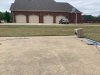
Speaker was angled at about 8 degrees so that the tweeter would be pointing on-axis with the microphone (well, as on-axis as it can be without burying the mic and pointing the mic at the DUT). Note that while the response was gated here, if I were to actually use this method I would move to the back yard where I could get the nearest reflection about 40 feet away which should get me down to around 20hz. So, this was more a sanity check test.
Pro: Invulnerability to reflection; I can get ever further out in my backyard. High resolution in to the very low frequency region.
Con: Outdoors. Diffraction effect of speaker changes due to the baffle doubling (via the mirror image effect). HF > 10khz seems to be a pain. From my research that's generally accepted as questionable. Though, I had decent results.
Phone placed at tweeter on baffle and used in 'selfie' mode to make sure the microphone was at the center of the image (trick I learned on another website).
Here's the result compared to Amir's:
And would it be possibel to do measurements to a 90- degree angle in this setup? Or would the angle of the speaker be tilted differently on every measurement?
OP
- Thread Starter
- #144
This seems to me the best compromise. I wonder, is it possible to lift the speaker in the air a bit so that you could negate the doubling of the baffle more?
And would it be possibel to do measurements to a 90- degree angle in this setup? Or would the angle of the speaker be tilted differently on every measurement?
I could lift the speaker off the ground. But that seems like it's then a compromise between ground plane and stand-mounted. Not sure. I'll give it a shot, though. My real concern there, though, is tilting the speaker. The higher off the ground I place it, the speaker's angle would have to be even greater to be aimed at the mic and I would worry about the speaker tipping forward and falling on its face.
In Test#1 the ripple is only visible from the range above 4kHz. In the GP measurement a strong ripple is already present from 400Hz.
Was the sound pressure during the measurement high enough to completely suppress the ambient noise even at high frequencies?
It would probably be an advantage to measure the speaker laterally next time.

Was the sound pressure during the measurement high enough to completely suppress the ambient noise even at high frequencies?
It would probably be an advantage to measure the speaker laterally next time.
OP
- Thread Starter
- #146
I re-tested the bookshelf on the 8.5 foot stand.
The result follows closely with Amir's but, again, I still have a discrepency in the 600-2khz region; where the NFS shows a bump from 600 to 1khz, my result is a bit flat and where the NFS results flatten from 1-2khz, my results show a mild bump. In the grand scheme, these differences are less than a couple dB. At this point, I think I'm willing to simply chalk this up to measurement method and call it a day. Even the early NFS measurements didn't overlay exactly on top of the Harman graphs. But I will attempt a closer measurement to see if this changes the trends I am getting in the response.

The result follows closely with Amir's but, again, I still have a discrepency in the 600-2khz region; where the NFS shows a bump from 600 to 1khz, my result is a bit flat and where the NFS results flatten from 1-2khz, my results show a mild bump. In the grand scheme, these differences are less than a couple dB. At this point, I think I'm willing to simply chalk this up to measurement method and call it a day. Even the early NFS measurements didn't overlay exactly on top of the Harman graphs. But I will attempt a closer measurement to see if this changes the trends I am getting in the response.
This looks better than the first measurement. Significantly fewer ripples in the measurement.At this point, I think I'm willing to simply chalk this up to measurement method and call it a day... But I will attempt a closer measurement to see if this changes the trends I am getting in the response.
Was there no wind during the measurements? If the background noise is high, the sound pressure should be increased accordingly during the measurement.
If the measuring program offers the possibility to average several measurements, this should be activated. This can considerably increase the signal-to-noise ratio of the measurement signal and the background noise. Simply average eight measurements and see if there is an improvement.
OP
- Thread Starter
- #148
When I did the first test I believe I did an average of 2 sweeps. The most recent one above had an average of 4 sweeps. I can't say what was different outside of that; potentially some wind or birds (seriously).
I may also start doubling to output voltage (assuming moderate sensitivity) to increase the SNR and post-correct the data for 2.83v/1m.
I may also start doubling to output voltage (assuming moderate sensitivity) to increase the SNR and post-correct the data for 2.83v/1m.
Think some deviations from Amir's curve is okay its just that the areas and number of amplitude they happen is bit surprising and what to conclude is bit funny, so as a one leg 8,5 feet long platform tube will create a hump between 1-2kHz and a three leg 5 feet platform come closest to resolute Amir's hump 600-1000Hz and that ground plane measurement is superior to resolute area up above 1kHz ") its interesting stuff and great thanks to Erin sharing his research.
its interesting stuff and great thanks to Erin sharing his research.

its interesting stuff and great thanks to Erin sharing his research.
Last edited:
dc655321
Major Contributor
- Joined
- Mar 4, 2018
- Messages
- 1,597
- Likes
- 2,236
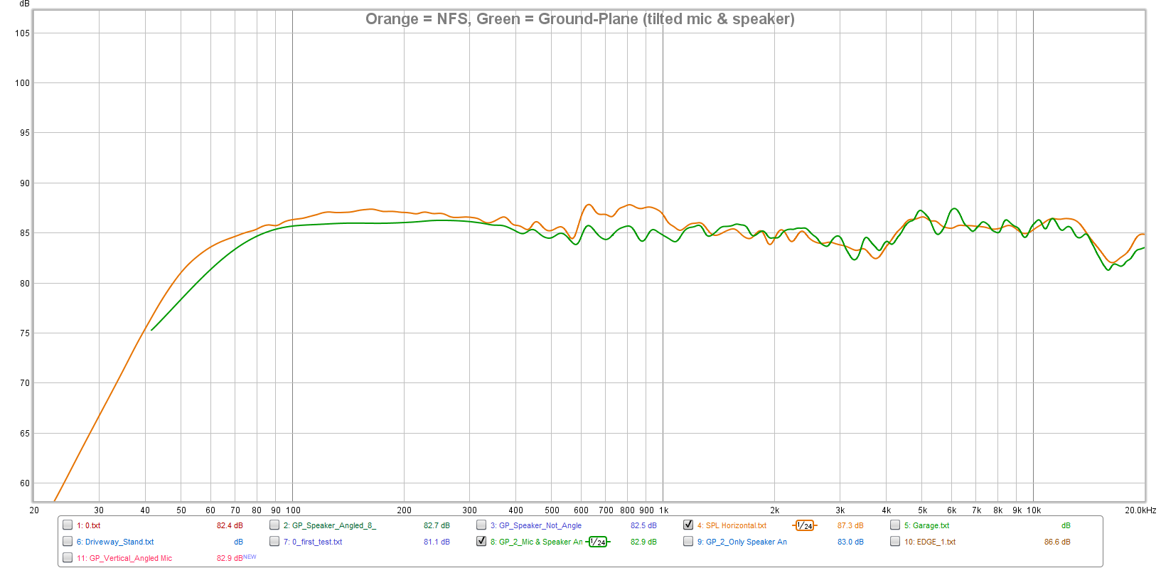
See below. This is all smoothed to 1/24 Octave.
It creates a lot of ripples (error). I wouldn't use this. *IF* I were to use the GP method I'd move it to the backyard which is a bit further away from any surface. Or just chop it at the first reflection and let it ride.
View attachment 60074
Thanks for humoring my request, and also for posting your measurements. Interesting!
The ~1dB pk-pk "noise" looks like a modulation at ~25Hz, some sort of analysis artifact (artificial) from the 0.1s impulse windowing.
Would you be able to post your raw measurement data (SPL vs Hz) somewhere for download so I could poke at it offline without further bothering you?
...The ~1dB pk-pk "noise" looks like a modulation at ~25Hz, some sort of analysis artifact (artificial) from the 0.1s impulse windowing...
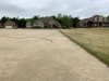
I could be wrong but think the riple is from natural boundarys, one can model boundary's in free spreadsheets from Jeff Bagby, to see only one boundary at a time cheat the spreadsheet set other boundary's to infinite as in below curves, the green 40feet curve is what Erin say he can reach in his backyard and the brown 14feet looks a bit like the ripple you talk about and could be the fence we see in the outdoor picture for Erin's 5 feet stand, blue 0,54feet curve is Elac DBR62 woofers center distance to ground plane.
OP
- Thread Starter
- #152
Alright, guys. I slept on this a bit and thought, "what if I take the merging approach and apply it to a ground plane measurement both indoors and outdoors" with the notion being that indoor GP measurement would be a way to help shore up any concern over HF response when measuring outdoors due to wind/noise/etc.
Below is a picture of the setup for the MF/HF GP portion:

(that tandem bike rocks!)
The nearest reflecting point was about 6 feet away. Here is the impulse response gated:

And here is the result compared against the NFS as well as my driveway GP measurement conducted yesterday where I was concerned some wind could be causing issues. Note: The SPL isn't an exact match because the distance may have been off a couple inches in either measurement; I'm just looking for trends.


And this is the result of the speaker on an 8.5 foot stand vs my GP measurement today and the NFS measurement:

All of these results of mine look pretty close to the NFS results. However, the striking difference is in the 600-1kHz region where the NFS shows approximately a +2dB difference over both my GP and outdoor 8.5 foot stand measurements.
So, do I quit obsessing over this difference? Do I call the GP method adequate and just carry on; potentially using the indoor GP measurement for mid/high frequency merging when conditions are a bit more windy/noisy? I am willing to do (2) sets of ground plane measurements if it saves me from breaking my back and/or wallet worrying over hoisting large speakers in to the air. And based on what I'm seeing in my results, the GP measurement matches as well as my high-stand mounted speaker measurements do to the NFS, other than the diffraction effect due to the mirror-image baffle. The only concern I currently have with the GP measurement is off-axis measurements. Does setting the speaker on a turntable that is lifted off the ground matter? I suppose I could just make a long 'table' to align with the turntable that runs the length of the path between speaker --> mic and place the mic on it at the other end. The height would alter the response some but if I'm only using the indoor measurement to avoid any concerns over very high frequency (>8kHz) then that is not of concern, either. I'll test this out later.
Below is a picture of the setup for the MF/HF GP portion:
(that tandem bike rocks!)
The nearest reflecting point was about 6 feet away. Here is the impulse response gated:
And here is the result compared against the NFS as well as my driveway GP measurement conducted yesterday where I was concerned some wind could be causing issues. Note: The SPL isn't an exact match because the distance may have been off a couple inches in either measurement; I'm just looking for trends.
And this is the result of the speaker on an 8.5 foot stand vs my GP measurement today and the NFS measurement:
All of these results of mine look pretty close to the NFS results. However, the striking difference is in the 600-1kHz region where the NFS shows approximately a +2dB difference over both my GP and outdoor 8.5 foot stand measurements.
So, do I quit obsessing over this difference? Do I call the GP method adequate and just carry on; potentially using the indoor GP measurement for mid/high frequency merging when conditions are a bit more windy/noisy? I am willing to do (2) sets of ground plane measurements if it saves me from breaking my back and/or wallet worrying over hoisting large speakers in to the air. And based on what I'm seeing in my results, the GP measurement matches as well as my high-stand mounted speaker measurements do to the NFS, other than the diffraction effect due to the mirror-image baffle. The only concern I currently have with the GP measurement is off-axis measurements. Does setting the speaker on a turntable that is lifted off the ground matter? I suppose I could just make a long 'table' to align with the turntable that runs the length of the path between speaker --> mic and place the mic on it at the other end. The height would alter the response some but if I'm only using the indoor measurement to avoid any concerns over very high frequency (>8kHz) then that is not of concern, either. I'll test this out later.
Last edited:
Cool indoor ground research there Erin, in a try to replicate Amir's 600-1000Hz ripple would it be a good idea as @ctrl suggested a page back lay enclosure on its side and think also try a enclosure upside down, reason for thinking is that some of that ripple is probably port leaking inteference plus mayby some diffraction and will change when port get coupled so close to the ground plane so maybe on its side plus upside down we can provocate a bit of that ripple be resoluted, below advanced plot is listening window for DBR62 EQ flat as pancake and still we have ripple in DI at 580Hz plus other clue as its a boosted diffraction point for woofer piston position, please dont feel pressed execute my suggestion but imagine yourself would love the last bit of resolution now we so lucky Amir own that nice reference robot.

Last edited:
OP
- Thread Starter
- #154
Well, if you have a keen eye you can see in my IR plots that I did do a vertical measurement (speaker laid on its side) for the reason you and ctrl mentioned (I somehow missed his comment about this). But I believe it didn’t tell me anything useful in this regard so I didn’t bother to mention it. I’ll look at it again.
dc655321
Major Contributor
- Joined
- Mar 4, 2018
- Messages
- 1,597
- Likes
- 2,236
I could be wrong but think the riple is from natural boundarys, one can model boundary's in free spreadsheets from Jeff Bagby, to see only one boundary at a time cheat the spreadsheet set other boundary's to infinite as in below curves, the green 40feet curve is what Erin say he can reach in his backyard and the brown 14feet looks a bit like the ripple you talk about and could be the fence we see in the outdoor picture for Erin's 5 feet stand, blue 0,54feet curve is Elac DBR62 woofers center distance to ground plane.
View attachment 60193
Thanks for this.
Learned something new today...
DDF
Addicted to Fun and Learning
- Joined
- Dec 31, 2018
- Messages
- 617
- Likes
- 1,360
Hi Erin,
Here's another data point, comparing a couple of my measurements of a raw Tangband woofer: indoors (blue) with ~ 4.5ms window vs outdoors (red) on an 8' ladder with 10 ms window. MLSSA+calibrated B&K 4133 and calibrated amp.
IME, if everything in the set up is OK (no reflections or vibrations), the only difference you should see will be due to the the FFT smoothing of the smaller window.
Are you using rectangular windows? If so, make sure window marker and cursor are set on zero crossings of the impulse response. If not, time aliasing occurs and false ripple creeps into the measurement. As a guess, this might explain your ripples.
OP
- Thread Starter
- #157
Are you using rectangular windows? If so, make sure window marker and cursor are set on zero crossings of the impulse response. If not, time aliasing occurs and false ripple creeps into the measurement. As a guess, this might explain your ripples.
Thanks for the reply.
I am using half Hanning windowing.
OP
- Thread Starter
- #158
Now that Amir has tested the Buchardt S400, which I just received yesterday (not the exact same speaker he tested; just the same model), I took the opportunity to do a little bit more testing. It has been raining off and on this morning so I proceeded with the garage-based ground plane measurements.
Before I show data let me say that this is NOT A FINAL TEST. This is simply an ad-hoc, "let's see if this looks logical" test to compare against Amir's data. My actual test results will be full range with higher resolution in the lower frequencies. Phew... OK. Read on.
Picture (the garage door was opened just to get some light for the photo; was shut during testing). The mic is ~ 2 meters from the speaker. The speaker itself is angled so that the tweeter has a direct line of sight with the microphone. I don't know what the angle is; I used my camera is selfie mode to put the speaker in the center of the frame and called it good enough.

Nearest reflection point from either the mic or the DUT was about 7 feet. Window of IR is about 8 ms wide.
I ran a series of tests but I'm providing what matters most. Note, I smoothed all data to 1/24 octave resolution.
Here is the FR comparison:

And to better see the difference, here is the NFS ÷ Ground Plane.

The delta is really quite nice. The resolution of my measurement isn't as high due to the 8ms window so that explains some of the low-mid frequency deviance. I was specifically looking for differences in the 600-2kHz region because that's where my Elac DBR62 differences showed up. I am seeing a similar trend here; my 600-1kHz region is a little bit lower, while my 1-2kHz region is a little bit higher. I mean, these are nitpicking levels. But assuming this is a trend caused by the NFS hardware itself then I'm OK with that conclusion and am happy to continue on. Assuming, of course, my off-axis measurements reveal similarly good matches with the NFS results.
**Of course, my results do not show the same 520Hz high-Q peak the NFS shows but that's simply because this, once again, is an indoors measurement with a relatively low window. Assuming my speaker has the same quality it will/should show up once I perform the GP test outdoors and can set my window to 40 ms. **
There could also be some very minor differences in HF due to imprecise aiming on my part; I didn't get the laser level out. I just eyeballed it to be on-axis horizontally. But the vertical reference axis was the tweeter itself.
Overall, however, this additional data set gives me a pretty good feeling about using the ground plane measurement. It's a really close match to the NFS result. I'll test outdoors when the weather permits and also conduct polars to see if there are any glaring issues.
Have to thank Amir again for posting his data. It's a really good way for me to sanity check my own methods and provide me even further confidence that what I am getting is quite good.
Before I show data let me say that this is NOT A FINAL TEST. This is simply an ad-hoc, "let's see if this looks logical" test to compare against Amir's data. My actual test results will be full range with higher resolution in the lower frequencies. Phew... OK. Read on.
Picture (the garage door was opened just to get some light for the photo; was shut during testing). The mic is ~ 2 meters from the speaker. The speaker itself is angled so that the tweeter has a direct line of sight with the microphone. I don't know what the angle is; I used my camera is selfie mode to put the speaker in the center of the frame and called it good enough.
Nearest reflection point from either the mic or the DUT was about 7 feet. Window of IR is about 8 ms wide.
I ran a series of tests but I'm providing what matters most. Note, I smoothed all data to 1/24 octave resolution.
Here is the FR comparison:
And to better see the difference, here is the NFS ÷ Ground Plane.
The delta is really quite nice. The resolution of my measurement isn't as high due to the 8ms window so that explains some of the low-mid frequency deviance. I was specifically looking for differences in the 600-2kHz region because that's where my Elac DBR62 differences showed up. I am seeing a similar trend here; my 600-1kHz region is a little bit lower, while my 1-2kHz region is a little bit higher. I mean, these are nitpicking levels. But assuming this is a trend caused by the NFS hardware itself then I'm OK with that conclusion and am happy to continue on. Assuming, of course, my off-axis measurements reveal similarly good matches with the NFS results.
**Of course, my results do not show the same 520Hz high-Q peak the NFS shows but that's simply because this, once again, is an indoors measurement with a relatively low window. Assuming my speaker has the same quality it will/should show up once I perform the GP test outdoors and can set my window to 40 ms. **
There could also be some very minor differences in HF due to imprecise aiming on my part; I didn't get the laser level out. I just eyeballed it to be on-axis horizontally. But the vertical reference axis was the tweeter itself.
Overall, however, this additional data set gives me a pretty good feeling about using the ground plane measurement. It's a really close match to the NFS result. I'll test outdoors when the weather permits and also conduct polars to see if there are any glaring issues.
Have to thank Amir again for posting his data. It's a really good way for me to sanity check my own methods and provide me even further confidence that what I am getting is quite good.
Last edited:
OP
- Thread Starter
- #159
Oh, sweet. I just noticed my dog (Rosie) is checking out the garage in the above picture.
Every time I go out there to test I have to usher her back inside because she always manages to find dead bugs laying at the garage opening and will eat them. She drives me nuts. But she's my buddy!
Every time I go out there to test I have to usher her back inside because she always manages to find dead bugs laying at the garage opening and will eat them. She drives me nuts. But she's my buddy!
OP
- Thread Starter
- #160
I made a post in the off-topic area asking about stepper motor advice. If any of you guys are knowledgeable in this area, please check the thread out and reply there (or PM me). I didn't post it in this thread on purpose because I thought I might have a better discussion outside of this thread, especially since some members don't even look in this sub-forum.
https://www.audiosciencereview.com/...ntable-design-for-measurement-purposes.12918/
https://www.audiosciencereview.com/...ntable-design-for-measurement-purposes.12918/
Similar threads
- Replies
- 18
- Views
- 1K
- Replies
- 29
- Views
- 4K
- Replies
- 25
- Views
- 1K
- Replies
- 17
- Views
- 2K