• WANTED: Happy members who like to discuss audio and other topics related to our interest. Desire to learn and share knowledge of science required. There are many reviews of audio hardware and expert members to help answer your questions. Click here to have your audio equipment measured for free!

Electrostatic Headphone Amplifier Review & Comparison

isiora

Member
Joined
Dec 10, 2020
Messages
10
Likes
31
The real issue was that Amir tested all the amps into far too low a load. In speaker amp terms it's like he tested them all into 1 ohm because that was the only high power load he had on hand.

With the solid state amps it "only" drastically reduced their maximum output. With the tube circuits it drastically raised their distortion as well.

The age of the amps, and consequently their power supply filter capacitors, is pretty much just related to the 60/120/etc hz hum and not distortion levels.

Correct, but it is not the only reason. It seems that he measured the amplifier as if it was a single ended, or heavily unbalancing the output stage. Infact the 2nd harmonic didn’t cancel out in his measurements.
 

kevin gilmore

Member
Joined
Feb 29, 2020
Messages
54
Likes
259
a bit more complicated than that
balanced in, balanced out, 6 db less 2nd harmonic vs 3rd harmonic
unbalanced in, balanced out, 6db less 3rd harmonic vs 2nd harmonic
most balanced amps do this.
 

isiora

Member
Joined
Dec 10, 2020
Messages
10
Likes
31
a bit more complicated than that
balanced in, balanced out, 6 db less 2nd harmonic vs 3rd harmonic
unbalanced in, balanced out, 6db less 3rd harmonic vs 2nd harmonic
most balanced amps do this.
Hi Kevin,

I'm not refer to in/out relationship, but to the two branch of balanced output. If I measure only one branch, for example L-, the even harmonics are much more higher than if I measure L-/L+ using a differnatial probe. Much more than 6dB. In theory, if the output stage is perfectly balanced, they cancel out totally. The differential measure is the sole valid, because our transducer (the headphone) sees a differential signal. The measurement I made and you saw above is a differential measurement, and as you can see the second harmonic is at almost -90dB!
I could show you this fact, measuring only one branch (e.g. L-).

Regards.
 
Last edited:

isiora

Member
Joined
Dec 10, 2020
Messages
10
Likes
31
unlike dynamic headphones, electrostatic headphones are balanced only. So measuring either of the amp outputs to ground is meaningless.

Yes, that's exactly what I'm saying, but that's what I suspect has been done instead.
Regard the single branch measurement, it was only an example that I replied to you about the second harmonic. The latter is low only thanks to the differential output, while it is much higher on each single branch, even more than 40dB of difference compared to differential mode, not just 6dB.
 
Last edited:
OP
amirm

amirm

Founder/Admin
Staff Member
CFO (Chief Fun Officer)
Joined
Feb 13, 2016
Messages
44,376
Likes
234,490
Location
Seattle Area
Correct, but it is not the only reason. It seems that he measured the amplifier as if it was a single ended, or heavily unbalancing the output stage. Infact the 2nd harmonic didn’t cancel out in his measurements.
The differential output pair were measured. AP's "unbalanced" input is floating so nothing was reference to ground but to the differential pair.
 

isiora

Member
Joined
Dec 10, 2020
Messages
10
Likes
31
The acoustic measurements confirm that something wrong there was with your original electrical measurements. Infact they show a much lower distorsion level, less than 0.05% THD @ >150Vrms (versus 1.8% THD @82Vrms). The sensitivity of the SR-303 at 1kHz is 100dB SPL at 100Vrms, and your graph starts at 104dB SPL, that isn't a medium level. The system reaches 112dB SPL (very dangerous for the ears) with only 0.16% of THD.
Curiously, up to 112dB the THD in the case of the tube amp is lower than in the case of the solid state amp. So in the most useful range, the tube amp has better THD performances.
But wait. If your system is calibrated then 112dB SPL are equivalent to 400Vrms, while the max output voltage of the 007t is 340Vrms (350Vrms for the 313, then this has more headroom). So the amplifier is clipping for limited power supply voltage, but the acoustic level is already very high.
 

isiora

Member
Joined
Dec 10, 2020
Messages
10
Likes
31
The differential output pair were measured. AP's "unbalanced" input is floating so nothing was reference to ground but to the differential pair.
From your words I did not understand which AP input you used for the measurements.
The AP has two inputs for each channel, one balanced and one unbalanced. The balanced input has an impedance of 100kOhm to ground for each side. The unbalanced one has an impedance of 100KOhm to the BNC shield and the shield in turn has 500Ohm || 1uF to ground (so it isn't that floating!).
Which of these two inputs do you have used?
If you have used the unbalanced input thinking it was floating then we found the problem. ;-)

P.S.: I never believed that 100kOhm could be such a big problem (it ‘only’ limits the max output to 135Vrms)
 
Last edited:

david85

Member
Joined
Sep 16, 2020
Messages
14
Likes
10
Error. I own the SR-007MKII and are great, and the SR-009s are the best headphones I've ever listened to. Although I've not listened to the high end Focals. For some reason Stax amps are not at the same level as their headphones. The problem here is that the alternatives to Stax are not very tempting. Gilmore's Blue Hawaii, and Spritzer's units have the price of an used car and not independent measurements.
You can try spritzer low to mid range offerings - octave , kgss klassik , movem
 

SpaceMonkey

Active Member
Joined
Jan 11, 2020
Messages
225
Likes
214
Could someone please explain why srd-7 sb is not good provided a pro mod was done on them?
 
Last edited:

TheGhostOfEugeneDebs

Member
Forum Donor
Joined
May 21, 2019
Messages
62
Likes
66
Could someone please explain why srd-7 sb is not good provided a mod was done on them?
For real, I still regard using a transformer as the best possible solution. I've listened to my 007mk2.5 on a few different amps through my ifi energizer and I just don't see why I'd get a dedicated Amp beyond this. They sound amazing through the hypex monoblocks, warmly colored but wonderful on the ragnarok 2 and like utter shit through the emotiva a100. Exactly like how speakers sound hooked up to these amps. Whatever magic the blue Hawaii can do, I'm certain I can get from a cheaper tube power amp and an energizer.
 

brimble

Active Member
Forum Donor
Joined
Oct 18, 2020
Messages
159
Likes
206
Location
Australia
For real, I still regard using a transformer as the best possible solution.
I think so too.

I've tried many Stax amps. To my ears (and this agrees with what measurements I've seen), all the solid state Stax energisers sound the same. The Stax tube energisers I've tried (which doesn't include the most expensive ones) sound slightly different and slightly worse. If you particularly like those then you can stop reading here. A transformer, even hooked up to a cheap power amp, sounds just like a solid state Stax energiser at low volumes, and at high volumes it's much less distorted.

Admittedly if I listened at those high volumes for long periods it would be bad for my ears, but it makes me happy to know I've got the extra headroom when I need it.
 

milosz

Addicted to Fun and Learning
Forum Donor
Joined
Mar 27, 2019
Messages
584
Likes
1,643
Location
Chicago
The Kevin Gilmore High Voltage Solid State (KGSSHV ) and the Carbon amplifiers sound excellent. Much better than any Stax amp. Also the Blue Hawaii sounds great.

Mjolnir audio makes an energizer that is supposed to sound much better than the Stax units, but I have not personally heard one.
 

kevin gilmore

Member
Joined
Feb 29, 2020
Messages
54
Likes
259
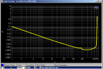
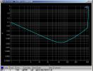
simmconn built and tested his carbon with an audio precision with an attenuator

first picture is with 450v power supplies
second picture is 400v power supplies
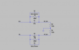
third picture is the hand built attenuator for the audio precision

comments from simmconn about how to trim the attenuator

Here is the attenuator I used (R3 and R4 are the AP input resistance, and not part of the attenuator). The R and C are rated at 500V or higher. The trimmers are adjusted with AP analog loop-back (repeat the below till both are satisfied)
1) Amplitude vs frequency response as flat as possible up to 100kHz balanced (I was able to reach ±0.02dB).
2) Set the AP output to balanced-grounded, short the AP +/- input to GND, one side at a time. Adjust the trimmers such that the response of the two attenuator arms are the same. I could use the common mode test feature on the AP to do this, but I figured the amount of work would probably be the same.
 

Attachments

  • 1014434510_A-A_THDN_VS_AMPL_newBuild_450V.PNG.872ac63bd54afddf231497e671f82eb0.png
    1014434510_A-A_THDN_VS_AMPL_newBuild_450V.PNG.872ac63bd54afddf231497e671f82eb0.png
    13 KB · Views: 212
  • 1014930400_A-A_THDN_VS_AMPL_newBuild_400V_LCH.PNG.d42728b34d598a5de37267baadc06a3c.png
    1014930400_A-A_THDN_VS_AMPL_newBuild_400V_LCH.PNG.d42728b34d598a5de37267baadc06a3c.png
    14 KB · Views: 210
  • Attn.thumb.PNG.dab95b2836a02de894b3a2cdf349f81f.png
    Attn.thumb.PNG.dab95b2836a02de894b3a2cdf349f81f.png
    37.7 KB · Views: 223
Last edited:
Top Bottom