• WANTED: Happy members who like to discuss audio and other topics related to our interest. Desire to learn and share knowledge of science required. There are many reviews of audio hardware and expert members to help answer your questions. Click here to have your audio equipment measured for free!

Double PCB amplifier problem hum need help!!

ModDIY

Addicted to Fun and Learning
Joined
Mar 26, 2020
Messages
663
Likes
424
Location
Canada
Hello everyone,

I have 2 purchased PCBs already assembled made by Zero Zone.

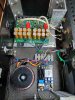
I have only one toroidal transformer of 100VA (18-0-18v), the transformer has no ground wire. If I plug in a mono PCB at a time, there is no hum, but as soon as I add the 2nd, the hum appears.

Screws on PCBs don't seem to have any grounds, so that suggests to me that PCBs aren't grounded. In addition there is a separate rectification on each PCB.

If you have any suggestions or ideas that can help me, that would be much appreciated. I also want to mention that I am quite new to electronics.

Thank you.
Denis.
 

Attachments

  • _IMG_000000_000000.jpg
    _IMG_000000_000000.jpg
    794.2 KB · Views: 139

Vini darko

Major Contributor
Joined
Jun 1, 2020
Messages
2,282
Likes
3,398
Location
Dorset England
Hi after spending some time looking at build. I notice it's a single ended input but they are wired seperatly into the amplifier modules. Try running a wire between the two negative inputs on the rca jacks ( negetive is the outer ring). That should establish common ground for the amp modules and may help with the hum.
 

802Lundgren

Member
Joined
Sep 21, 2020
Messages
6
Likes
4
Location
Sweden
Hi,
wow, interesting build. It's great to DIY and you are obviously brave enough to do that. However some of what I can see looks like its not built to last. like for example the solder joints on the speaker terminals? Also that kind of terminal strip is not a good thing, the tranformer wires are most likely solid and it is not optimal to use a terminal strip like that. And remember Safety first, if I were you I would always have one hand in my pocket even just being close to that build. Ok, sorry about that, on to your problem.

Is the RCA ground connections isolated from chassis? is there still hum if you short the RCA inputs?
It looks like secondary middle windings are joined in that terminal strip and then connected to each amplifier board around were it says AC IN, are you sure thats how it should be done?
Do you have a picture of the board schematics?

Again I don't mean to dis encourage you, but safety first and good luck.
 
OP
ModDIY

ModDIY

Addicted to Fun and Learning
Joined
Mar 26, 2020
Messages
663
Likes
424
Location
Canada
Hi,
wow, interesting build. It's great to DIY and you are obviously brave enough to do that. However some of what I can see looks like its not built to last. like for example the solder joints on the speaker terminals? Also that kind of terminal strip is not a good thing, the tranformer wires are most likely solid and it is not optimal to use a terminal strip like that. And remember Safety first, if I were you I would always have one hand in my pocket even just being close to that build. Ok, sorry about that, on to your problem.

Is the RCA ground connections isolated from chassis? is there still hum if you short the RCA inputs?
It looks like secondary middle windings are joined in that terminal strip and then connected to each amplifier board around were it says AC IN, are you sure thats how it should be done?
Do you have a picture of the board schematics?

Again I don't mean to dis encourage you, but safety first and good luck.

I will try to answer point by point.

- There were solder cables on the speaker terminal blocks, I cut and left one end of each wire and soldered the new ones on top, I don't usually do that, I wanted to save time, but it's stronger than it looks.

- The terminal strip is of good caliber, apparently good for 15 A.

- Yes the RCAs are isolated from the chassis. Yes the hum persists even with the 2 RCA grounds connected together.

- I am sure of the connections. I don't have a plan or diagram, I will find pictures. If I connect only one channel at a time, the sound is superb, no hum or hiss, it is as soon as I connect the two sets that the hum occurs.

Yes thank you for reminding me, I always work just with one hand when I put the tension on, I am very careful. I come back with more details of the connections.

Thank you!
Denis

Ps: The fuse is integrated in the AC socket.
 
Last edited:

802Lundgren

Member
Joined
Sep 21, 2020
Messages
6
Likes
4
Location
Sweden
Hello,
ok, Good to check things twice. I meant IF there is nothing connected to the input, or even if the input is shortd to gnd, is there still a problem?
Well those kind of terminals sometimes they just have a screw pressing down on to the wire and that is not so good.
 

Doodski

Grand Contributor
Forum Donor
Joined
Dec 9, 2019
Messages
21,606
Likes
21,883
Location
Canada
Are you sure those RCA input wires are making good contact at the PCBs? Have you swapped both sides or just one? Need a schematic to continue or a wiring diagram at best. :D
 

mansr

Major Contributor
Joined
Oct 5, 2018
Messages
4,685
Likes
10,705
Location
Hampshire
Nothing to do with the hum, but it looks like you've used green/yellow wire for something other than safety ground. Do not ever under any circumstance do that.
 
OP
ModDIY

ModDIY

Addicted to Fun and Learning
Joined
Mar 26, 2020
Messages
663
Likes
424
Location
Canada
Nothing to do with the hum, but it looks like you've used green/yellow wire for something other than safety ground. Do not ever under any circumstance do that.

Alright it's noted. I recovered the wires from an AC cable.

I fixed the HUM issue. I simply added a 2nd transformer, because there is a diode bridge on each PCB. On another forum, I was told that it took 2 transformers in this case. In short there was no hum, it's very quiet even the ear stuck on the hp.

Thank you all for your help. :)
 
Top Bottom