• WANTED: Happy members who like to discuss audio and other topics related to our interest. Desire to learn and share knowledge of science required. There are many reviews of audio hardware and expert members to help answer your questions. Click here to have your audio equipment measured for free!

Audiophonics PRE-TC10 preamp with tone controls - review and measurements

Rate this preamplifier with tone controls

  • Poor

    Votes: 1 5.3%
  • Not terrible

    Votes: 2 10.5%
  • Fine

    Votes: 12 63.2%
  • Excellent

    Votes: 4 21.1%

  • Total voters
    19

pma

Major Contributor
Joined
Feb 23, 2019
Messages
4,602
Likes
10,769
Location
Prague
I have decided to buy and measure this preamplifier with tone controls, supplied by Audiophonics. It can be ordered here:


and it costs 49.92 EUR without VAT and 59.90 EUR with VAT (depending on country). I paid 72.10 EUR total together with the DPD shipment. The preamp has arrived in less than one week from placing the order.

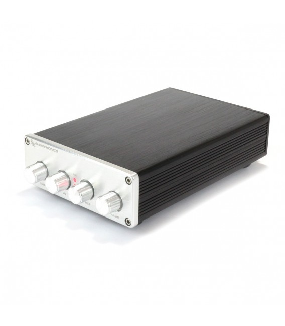
Photos of the product and first impressions

First I made several photos of the preamp and also some photos with replaced top cover.

IMG_4201_PRE-TC10_front.JPG


IMG_4201_PRE-TC10_angle.JPG


On the front panel, we can see (left to right) bass control pot, mid control pot, treble control pot and volume pot. If the treble control pot is set full left, there is a switch that bypasses the tone controls. This is very useful.

IMG_4201_PRE-TC10_rear.JPG


On the rear panel we can see input and output RCA connectors, AC mains receptacle and the power switch.

IMG_4201_PRE-TC10_topopen.JPG


IMG_4201_PRE-TC10_sideopen.JPG


We can see that the EURO 230V socket is connected only to L and N, though it is a 3-prong socket. This should not be so, strictly from view of valid standards. On the other hand, PE ground loop issues of this SE signal device are avoided. The manufacturer should have use a 2-prong EURO socket, however.

Measurements

After a visual inspection I have connected the preamp to the 230V ac mains net. The preamp started to work as expected and as it should, so I started to make measurements. My system uses Topping D10s as a signal source and E1DA Cosmos ADC as a measuring instrument, used in stereo mode, Left channel, 4.5V input range, with 830 ohm input impedance.

Frequency responses

It is a tone control circuit so the frequency responses are very important. First, let's see actions of bass and treble controls and of a bypass switch.

Audiophonics PRE-TC10 - freqresps2.png


The middle frequency of the controls is centered around 700Hz, which is lower than usual 1kHz.

Now, with addition of action of the mid controls:

Audiophonics PRE-TC10 - freqresps4-all.png


Mid controls center is about 1kHz.


Noise and distortion

This is the noise measured at preamp output, with controls in the middle position and minimum volume.

Audiophonics PRE-TC10 - noise.png


Output noise is 8.95uV/BW45kHz, 6.84uV/BW22kHz, 5.31uVA.


THD and THD+N at 1kHz/2V with tone controls bypassed
Audiophonics PRE-TC10 - THD1k.png


THD and THD+N at 1kHz/2V with tone controls in the middle

Audiophonics PRE-TC10 - THD1k-withtonecntr_mid.png


We can see rise of the distortion when tone controls are activated.

THD vs. frequency at 2V with tone controls activated and bypassed

Audiophonics PRE-TC10 - THDfreq-withtonecntr_mid.png


THD is very low with the controls bypassed and goes quite higher when controls are activated, especially below 1kHz. The rise of distortion with tone controls activated is a result of designers/manufacturers choice of capacitors in tone controls - they use MLCC ceramic capacitors that are known for their non-linearity. They save space at the expense of higher distortion.

Conclusion

Audiophonics PRE-TC10 may be a useful product for someone who needs tone controls preamp at affordable price. Built quality is good, with exception of the control knobs that collide a bit with the front panel when turned. Hopefully, it can be fixed by pulling the knobs a bit, as they are not fixed by screws.
 
Last edited:
OP
pma

pma

Major Contributor
Joined
Feb 23, 2019
Messages
4,602
Likes
10,769
Location
Prague
Some more info:

Input impedance: 30 - 100 kohm, depending on volume pot position
Output impedance: 100 ohm
Max. output voltage: 9.1 Vrms
Crosstalk at 1kHz: -80dB
Crosstalk at 10kHz: -60dB

THD and THD+N vs. output level at 1kHz, controls bypassed

Audiophonics PRE-TC10 - THDlevel-cntrbypass.png


Sound

It definitely helps to get more optimal frequency balance from older vinyl records and from cassettes. It also help in new recordings, where the mastering engineer did not do a good job, like too emphasized bass.
 
Last edited:

holla

Member
Joined
Jul 19, 2022
Messages
25
Likes
21
Is it legal to have a mains-powered device like this with no earth connection? I am only dimly aware of the legislation but I thought non-earthed gear had to be "double insulated".
 

Talisman

Addicted to Fun and Learning
Forum Donor
Joined
Mar 27, 2022
Messages
947
Likes
2,771
Location
Milano Italy
Thanks PMA, it is very useful to have measurements even of cheap but potentially well measuring equipment, as in this case.
With the controls bypassed the performances are transparent, with the controls inserted it is possible to correct gross errors of FR. An economic but functional product.
 
  • Like
Reactions: pma
OP
pma

pma

Major Contributor
Joined
Feb 23, 2019
Messages
4,602
Likes
10,769
Location
Prague
Is it legal to have a mains-powered device like this with no earth connection? I am only dimly aware of the legislation but I thought non-earthed gear had to be "double insulated".

It is "legal" (in conformance with safety standards) as long as it is a class II device with 2-prong socket or fixed cord. Here, the transformer looks OK and wiring as well. But the 3-prong socket is against the safety standards for the class II device, it should have been a 2-prong socket, like the one below.

1684836201647.png
 
OP
pma

pma

Major Contributor
Joined
Feb 23, 2019
Messages
4,602
Likes
10,769
Location
Prague
The question is whether the tone control can be easily bypassed if you only want the gain < 13 dB.

Yes!

View attachment 287534
Please see post #1,

On the front panel, we can see (left to right) bass control pot, mid control pot, treble control pot and volume pot. If the treble control pot is set full left, there is a switch that bypasses the tone controls. This is very useful.
BTW, I measured gain 14.80dB with controls bypassed.
 

holla

Member
Joined
Jul 19, 2022
Messages
25
Likes
21
It is "legal" (in conformance with safety standards) as long as it is a class II device with 2-prong socket or fixed cord. Here, the transformer looks OK and wiring as well. But the 3-prong socket is against the safety standards for the class II device, it should have been a 2-prong socket, like the one below.

View attachment 287535
Thanks for this clarification. As I said, I do not quite know what counts as Class II double-insulation. I can't see much that would protect the user if e.g. the live connection failed and contacted the chassis. But I do not mean to derail the thread so I shall shut up!
 

maty

Major Contributor
Joined
Dec 12, 2017
Messages
4,600
Likes
3,170
Location
Tarragona (Spain)
Pavel, now you can do a new test of op-amps like years ago in diyaudio. I have a quieter amp and have further optimized my second system so it is supposed to be even easier for me than then.

What do you think of the OPA828 as an alternative?


Attachments

  • OPA828.png
    OPA828.png
    362.8 KB · Views: 53
  • OPA828-joseph-k.png
    OPA828-joseph-k.png
    44.8 KB · Views: 59
  • Like
Reactions: pma
OP
pma

pma

Major Contributor
Joined
Feb 23, 2019
Messages
4,602
Likes
10,769
Location
Prague
Pavel, now you can do a new test of op-amps like years ago in diyaudio. I have a quieter amp and have further optimized my second system so it is supposed to be even easier for me than then.

What do you think of the OPA828 as an alternative?

Yes, OPA2828 (dual version of 828) should definitely work well in this preamp, with a socket adapter

1684839951574.png


It has low noise, high GBW, high slew rate and is unity gain stable. A good candidate for those who want to play, definitely.

1684840115769.png
 
OP
pma

pma

Major Contributor
Joined
Feb 23, 2019
Messages
4,602
Likes
10,769
Location
Prague
Thanks for this clarification. As I said, I do not quite know what counts as Class II double-insulation. I can't see much that would protect the user if e.g. the live connection failed and contacted the chassis. But I do not mean to derail the thread so I shall shut up!

It is OK, as long as the class II device is designed and built properly. Class I for a device like this, which has both single-ended input and output, is always source of troubles, because then groundloops, when connected with another class I device are inevitable and will degrade S/N. I can measure an insulation resistance of L and N pins vs. chassis with a special insulation tester, if you like.

Edit: I did the 500Vdc insulation test, there was no measurable leakage current.
 
Last edited:

Matias

Master Contributor
Forum Donor
Joined
Jan 1, 2019
Messages
5,072
Likes
10,923
Location
São Paulo, Brazil
Great review, thanks!
 
  • Like
Reactions: pma
OP
pma

pma

Major Contributor
Joined
Feb 23, 2019
Messages
4,602
Likes
10,769
Location
Prague
Some measurements with oscilloscope

1) Maximum output voltage before clipping is 9Vrms
PRE-TC10_maxout.png


2) 10kHz square response
PRE-TC10_10ksq.png


3) Slew rate - measured as 21V/us, defined by LME49720 used
PRE-TC10_SR.png


These measurements were done with tone controls bypassed (treble knob full left, controls switched off).
The preamp would be able to drive power amps that have lower gain, due to its 9Vrms clean output.

The preamp transfers DC in full amplitude, that means that it works from 0Hz without LF attenuation and with no phase shift at low frequencies.
PRE-TC10_spsquare.png
 
OP
pma

pma

Major Contributor
Joined
Feb 23, 2019
Messages
4,602
Likes
10,769
Location
Prague
Warning!

Unfortunately, I found a flaw in the circuit. Supply voltage at LME49720 pins is +14V and -23.13V. This makes 37.13V total between +Vs and -Vs and it exceeds datasheet absolute maximum rating, which is 36V.

1684913409673.png


The opamps works yet, but the conditions are dangerous and may result in premature failure. I need to check the LM337 stabilizer circuit, which seems not to be working.
 

antcollinet

Master Contributor
Forum Donor
Joined
Sep 4, 2021
Messages
7,679
Likes
12,940
Location
UK/Cheshire
It is OK, as long as the class II device is designed and built properly. Class I for a device like this, which has both single-ended input and output, is always source of troubles, because then groundloops, when connected with another class I device are inevitable and will degrade S/N. I can measure an insulation resistance of L and N pins vs. chassis with a special insulation tester, if you like.

Edit: I did the 500Vdc insulation test, there was no measurable leakage current.
However - If I were inspecting this device I would deem it non compliant, not only for the 3 pin connector (which is more technical than actual safety). There is nothing stopping the mains input wiring contacting the case (or moving to within 5.5mm of it), at which point there is only the single insulation of the wire protecting the user.

It's difficult to see from the photos, but one of the wires might violate the 5.5mm clearance by design due to its position on the PCB.

Another possible area for concern would be the clearance between the protruding pins on the underside of the PCB and the bottom surface of the enclosure.


I have, however voted the unit "fine" for performance.
 
OP
pma

pma

Major Contributor
Joined
Feb 23, 2019
Messages
4,602
Likes
10,769
Location
Prague
Warning!

Unfortunately, I found a flaw in the circuit. Supply voltage at LME49720 pins is +14V and -23.13V. This makes 37.13V total between +Vs and -Vs and it exceeds datasheet absolute maximum rating, which is 36V.


The opamps works yet, but the conditions are dangerous and may result in premature failure. I need to check the LM337 stabilizer circuit, which seems not to be working.

!! Fixed !!

The no-name "xifi" LM337 used by the manufacturer was not working. It had internal short. What a shame, I expect the product control does not check opamp supply voltages. I found it when measuring the output swing with the oscilloscope, negative half worked down to more than -20Vp ...., without clipping.

This is the wrong one
IMG_4201_PRE-TC10_topopen_LM337failed.JPG


Fixed by the old DDR B3370V (LM337 equivalent), Thorsten Loesch would be happy)
IMG_4201_PRE-TC10_topopen_LM337repair.JPG


Fixed, LME49720 have survived supply overvoltage ....

Now I will to have re-measure noise and THD spectrum, I expect even lower level of mains multiples residuals due to negative voltage regulator working as it should!
This is the way to do technical reviews, check everything and never give up! :cool::D
 
OP
pma

pma

Major Contributor
Joined
Feb 23, 2019
Messages
4,602
Likes
10,769
Location
Prague
Now I will to have re-measure noise and THD spectrum, I expect even lower level of mains multiples residuals due to negative voltage regulator working as it should!

Done, the noise and THD/THD+N at 1kHz remained similar, THD and THD+N at high frequencies has improved after repair. THD is vanishingly low, noise is a bit higher, due to 14.80 dB circuit gain.

Audiophonics PRE-TC10 - THDNfreq-bypass_repaired.png
 
Top Bottom