Hello Trung, I'm a fan of your mods. I do mods myself as well.
The decoupling capacitors you are referring from the documentation are these:
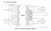
View attachment 352916
Those SMD Eletrolytics you replaced do not seem to be part of TI original design. They don't exist on any other TPA3255board I've seen.
They normally lie under the heatsink and right next to the TPA3255/51 chip and serve to decouple/bypass the big bulk power capacitors.:
View attachment 352917
View attachment 352919
View attachment 352920
View attachment 352921
In the case of A07 Max, and Fosi V3 they are placed on the opposite side to the chip(because of thermal design improvements on those amps) but still very closed to the chip and connected thought vias.
I have not fully analyzed the design of the A07 Max, but it looks like those 4 (2x 1uF and 2x 0.1uF) SMD Electrolytic capacitors are on the output audio path, or used by the relay circuit. So they don't withstand the Power supply voltage, only the output voltage.
If that's the case then replacing them with better capacitors might improve the sound quality of the amp. You replaced them with ceramic capacitors and noticed lower noise. What if replaced with MLCC or film caps? I think you can manage to solder them to those SMD pads.
I'll open up my A07 Max this weekend and try to figure out what those caps are doing and where they are connected (in reference to the TI schematics)