I have just ordered the NA2M-D0B-Tx version, with Male XLR, which makes more sense to me. I will make my own measurements, including CMRR measurement and distortions and frequency response at lower level, up to -3dBu as per specification. The review posted here does not make much sense to me. Yes I am buying the product only to make my own measurements and post them in a new thread.

-
WANTED: Happy members who like to discuss audio and other topics related to our interest. Desire to learn and share knowledge of science required. There are many reviews of audio hardware and expert members to help answer your questions. Click here to have your audio equipment measured for free!
You are using an out of date browser. It may not display this or other websites correctly.
You should upgrade or use an alternative browser.
You should upgrade or use an alternative browser.
Neutrik NA2F-D0B-TX XLR to RCA Adapter Review
- Thread starter amirm
- Start date
- Joined
- Nov 3, 2020
- Messages
- 629
- Likes
- 1,056
If I understand correctly, 1V would be approximately +3dBu, which according to their spec is already oversaturated at those levels. The sweep would probably look better at 0.5V (closer to the spec), but -3dBu seems way too low for anything useful. (Sorry if this is redundant info, I didn’t read the whole thread.)That is likely there because the transformer massively distorts at low frequencies:

Last edited:
But why do you think Neutrik specs the minimum source impedance at 200 Ohms?we need to de-rate that thingy significantly and give it best working conditions:
- lowest possible drive impedance (40Ohm AP output is fine)
-3dBu is about -5dBV, so this is really meant for consumer level devices (ie -10dBV=0VU).If I understand correctly, 1V would be approximately +3dBu, which according to their spec is already overstated at those levels. The sweep would probably look better at 0.5V (closer to the spec), but -3dBu seems way too low for anything useful. (Sorry if this is redundant info, I didn’t read the whole thread.)
It does make more sense, but then it's just a regular DI box, which there are plenty, with better performance, more features, more flexibility. The other way around is a bit more unique with less options to choose from. I do wonder if these are bidirectional since it's 1:1 but the shown filter may suggest otherwise. It does make sense to have a High pass at the input to avoid hitting the trnsfo with subsonics, but this is a bit high cutoff as measured. Can you also measure the effect of source impedance on that filter?I have just ordered the NA2M-D0B-Tx version, with Male XLR, which makes more sense to me. I will make my own measurements, including CMRR measurement and distortions and frequency response at lower level, up to -3dBu as per specification. The review posted here does not make much sense to me. Yes I am buying the product only to make my own measurements and post them in a new thread.
I suggest, for noise performance , do a comparison test. On one hand, with a 5 meter single ended quality cable between source and measuring equipment, running at 50mV or less, and on the other hand, using this device to convert to balanced at source, then a 5m balanced cable to measuring gear, at a matched level.I have just ordered the NA2M-D0B-Tx version, with Male XLR, which makes more sense to me. I will make my own measurements, including CMRR measurement and distortions and frequency response at lower level, up to -3dBu as per specification. The review posted here does not make much sense to me. Yes I am buying the product only to make my own measurements and post them in a new thread.
After all, that's what this device is for!
otherwise, one can easily just wire single ended to hot pin, and ground the cold.
This device convers to balanced, to tackle a possible NOISE issue, if it can achieve that, it has done its job.
small distortions on pro gear, is neither here nor there, specially at this price bracket.
OP
- Thread Starter
- #167
I added -3dBu tests to the review. The graph you want to look at is this one which is with the device just connected on the XLR side alone to the analyzer and loading it way down due to very low impedance:
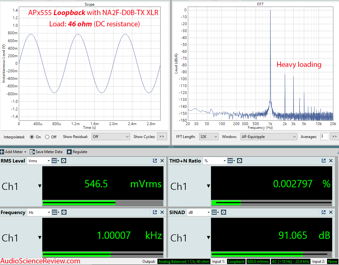
Good luck finding an audio device that is happy to drive just 46 ohm DC resistance. We are talking speaker level impedances here folks, not line level!
Good luck finding an audio device that is happy to drive just 46 ohm DC resistance. We are talking speaker level impedances here folks, not line level!
Thanks! may you explaine a bit more your impedance comment? I am not sur what you mean, maybe just not thinking it trough or it’s the vocabulary. what do you mean by “loading it way down” and then “drive just 46 ohm dc resistance” Sorry in my word the load is what you connect this to, and the “driving” impedance would be the output impedance of the source. What is the source impedance, and. what is the input impedance when looping back? 46 ohm is indeed low for a line level output on xlr but not, in an extreme kind of way, And I believe you mentioned on the previous tests it was 49 ohms. How is it loading “way down”. For example Shiit Modius have an output impedance of 75 ohms, my Radial DI box has 150, the RME ADI states 200. Most modern audio interfaces are around or below 100. If you are talking the line input of the AP then I am even more confused why you would do that,indeed it would not make sense. And still I don’t fully understand why you felt the need to load it way down when the unit is specifes at 200. If 46 is way down, what is normal for your line level AP tests?I added -3dBu tests to the review. The graph you want to look at is this one which is with the device just connected on the XLR side alone to the analyzer and loading it way down due to very low impedance:
Good luck finding an audio device that is happy to drive just 46 ohm DC resistance. We are talking speaker level impedances here folks, not line level!
OP
- Thread Starter
- #169
I didn't load it down. The adapter did. Its *input* DC resistance is just 47 ohm. So when I connected it to the output of the analyzer, it distorted it as it expect much higher impedance. If you took your Modius DAC and connected this adapter to its output, its distortion would shoot through the roof as it wants a load that is at least 10X higher than its own impedance.And still I don’t fully understand why you felt the need to load it way down when the unit is specifes at 200.
OK maybe I don't fully get it still, but It's a 1:1 impedance transformer, designed to be roughly, as I understand, impedance matched at the input. i may get to read a bit more and may be in the wrong but I don't think your analyser is suppose to see this as a 46 ohm load It should see the actual load, the line in. It's a passive device, if you had a standard 10k at the input, what would you get at the output? That'd be much worst wouldn't it? That said, well in the end, yes, it adds distortion, It have 0.006 THD+N in it's linear operation range. Not great. Don't think I am here to praise the product but to understand it a bit more.I didn't load it down. The adapter did. Its *input* DC resistance is just 47 ohm. So when I connected it to the output of the analyzer, it distorted it as it expect much higher impedance. If you took your Modius DAC and connected this adapter to its output, its distortion would shoot through the roof as it wants a load that is at least 10X higher than its own impedance.
Last edited:
Thanks!I added -3dBu tests to the review. The graph you want to look at is this one which is with the device just connected on the XLR side alone to the analyzer and loading it way down due to very low impedance:
Good luck finding an audio device that is happy to drive just 46 ohm DC resistance. We are talking speaker level impedances here folks, not line level!
I didn't load it down. The adapter did. Its *input* DC resistance is just 47 ohm. So when I connected it to the output of the analyzer, it distorted it as it expect much higher impedance. If you took your Modius DAC and connected this adapter to its output, its distortion would shoot through the roof as it wants a load that is at least 10X higher than its own impedance.
The DC resistance of a transformer is always much lower than the impedance at for instance 1KHz, any idea what it is at 1KHz? it should be around 600 ohm?
But indeed that the AP555 gets to much load from this thing is not a good sign..! weird!
Winding inductance is very high, in case of the link transfomer I have it is 4H. Transformer is a transformer, and as such it transforms impedance from secondary to primary. Blow the typical input impedance of the link transformer loaded with 10kohm resistor.The DC resistance of a transformer is always much lower than the impedance at for instance 1KHz, any idea what it is at 1KHz? it should be around 600 ohm?
But indeed that the AP555 gets to much load from this thing is not a good sign..! weird!

It is the transformer impedance nonlinearity that matters, not the impedance magnitude value.
I can see that @amirm has just measured the adapter at lower level -3dBu. The additional distortion in the output of AP is due to interaction of transformer nonlinearity with AP output impedance, that´s it. If he measured at 50Hz, the distortion in AP output would be huge.
Last edited:
I agree that THD at 1kHz as shown in post #1 is too high. I have just checked the link transformer I have here and the THD1kHz is totally acceptable

and it still remained about 0.003% at +13dBV. I will see what the Neutrik adapter would show later.
and it still remained about 0.003% at +13dBV. I will see what the Neutrik adapter would show later.
KSTR
Major Contributor
Do they?But why do you think Neutrik specs the minimum source impedance at 200 Ohms?
Actually, there never is any minimum source impedance spec for transformers, only a maximum source impedance.
Golden rule #1 for successful application of audio transformers: Drive it with as low impedance as possible (and properly terminate the output for higher frequencies to get flat FR with no overshoot).
The lower the source impedance the better the low-frequency behavior. We want the inductance to be dominant against the DC resistance because the latter is basically a parasitic. Obviously, when driving the xformer below its LF cutoff (where inductance gets too low) the source is loaded with close to the DC resistance and that may stress the source. Can be filed under mis-use, though. Same goes for overdriving. They can even have chaotic behavior under overdrive, this can be seen as the low-frequency waveform breaking down, being "folded over" when reaching a certain level, but flipping back at a much lower level. A bifurcation problem -- and it sounds very nasty.
In the extreme case you drive the transformer with a negative source impedance equaling its DC resistance. That's what AP and other do with their clever feedback circuits for transformers (including a DC resistance vs temperature tracking with an extra winding for that purpose).
Transformers are very much like speakers: If you need them to go loud and deep with low distortion you need to go BIG.
Even the ingenious active "zero-field" technique (driving the xfmr. with current and sensing the short-circuit current on the secondary side) doesn't change that by much and has bunch of drawbacks anyway.
Exactly.Golden rule #1 for successful application of audio transformers: Drive it with as low impedance as possible (and properly terminate the output for higher frequencies to get flat FR with no overshoot).
Vladimir Filevski
Addicted to Fun and Learning
- Joined
- Mar 22, 2020
- Messages
- 592
- Likes
- 803
True, but what about the built-in high-pass filter? Should it be properly loaded (200/600 ohms as per specification) in it's input, to work as designed?Golden rule #1 for successful application of audio transformers: Drive it with as low impedance as possible ...
Edit: also, loaded at it's output with 2k/10k ?
Last edited:
The lower the source impedance the better the low-frequency behavior. We want the inductance to be dominant against the DC resistance because the latter is basically a parasitic. Obviously, when driving the xformer below its LF cutoff (where inductance gets too low) the source is loaded with close to the DC resistance and that may stress the source. Can be filed under mis-use, though. Same goes for overdriving. They can even have chaotic behavior under overdrive, this can be seen as the low-frequency waveform breaking down, being "folded over" when reaching a certain level, but flipping back at a much lower level. A bifurcation problem -- and it sounds very nasty.
Klaus, would you have an explanation for this (50Hz plot):

The transformer is driven from Zout close to 0ohm with 250mA current capability. At the knee, ratio of even/odd harmonics is changing. Thank you.
Thanks, it does make sense. I did read this spec maybe incorrectly as it wanted to be driven between 200 and 600 and loaded between 2K and 10k, not sure what they mean.:Do they?
Actually, there never is any minimum source impedance spec for transformers, only a maximum source impedance.
Golden rule #1 for successful application of audio transformers: Drive it with as low impedance as possible (and properly terminate the output for higher frequencies to get flat FR with no overshoot).
The lower the source impedance the better the low-frequency behavior. We want the inductance to be dominant against the DC resistance because the latter is basically a parasitic. Obviously, when driving the xformer below its LF cutoff (where inductance gets too low) the source is loaded with close to the DC resistance and that may stress the source. Can be filed under mis-use, though. Same goes for overdriving. They can even have chaotic behavior under overdrive, this can be seen as the low-frequency waveform breaking down, being "folded over" when reaching a certain level, but flipping back at a much lower level. A bifurcation problem -- and it sounds very nasty.
In the extreme case you drive the transformer with a negative source impedance equaling its DC resistance. That's what AP and other do with their clever feedback circuits for transformers (including a DC resistance vs temperature tracking with an extra winding for that purpose).
Transformers are very much like speakers: If you need them to go loud and deep with low distortion you need to go BIG.
Even the ingenious active "zero-field" technique (driving the xfmr. with current and sensing the short-circuit current on the secondary side) doesn't change that by much and has bunch of drawbacks anyway.
Source/load impedance in Ohm: 200/2k, (600/10k)
I was not so much wondering about the behaviour of the Transfo but more the behaviour of the high past filter, It would be part of the cutoff calculation no? 600 make sense as a max, there is simply no line level source higher than that, but the first set of number I don't know what they mean by the first one.
Last edited:
I am no expert.Klaus, would you have an explanation for this (50Hz plot):
View attachment 293451
The transformer is driven from Zout close to 0ohm with 250mA current capability. At the knee, ratio of even/odd harmonics is changing. Thank you.
At low levels, the distortion is due to hysteresis. At some stage (the knee) it starts to distort due to overloads, two causes, producing distortions.
my 2 pence.
Similar threads
- Poll
- Replies
- 150
- Views
- 19K
- Replies
- 6
- Views
- 898
- Poll
- Replies
- 88
- Views
- 19K
- Poll
- Replies
- 53
- Views
- 11K
- Replies
- 158
- Views
- 24K