- The load is 8 ohms approx on a 4:1 off 120VAC, so call it 200 watts. Very appropriate loading for 10,000 or 100,000uF.
- The resistor is the resistor that was put in the path to show the current after the bridge that will go into the C\load (which of course you can reflect back to the input)
- If I include transformer L, that would be a FILTER, but I was trying to illustrate the real harmonic content of the load, because if you filter that content, the voltage must drop, as that power is lost
- These are all pure 60Hz, 0 distortion AC source. I am not distorting or contradicting anything. I am showing real world linear power supply (sans the perfect AC line and perfect transformer). I could add leakage inductance to the transformer, and some eddy losses, and model a source impedance and resistance on the AC line if you would like, but that will just prove my point even more about DC voltage at the caps dropping
- These are all the same by the way, all I changed was the capacitance, so how are the first 2 any different? The only difference in the last simulation is the simulation is not long enough so the large capacitor charging time impacts the displayed spectrum as there is too much not steady state.
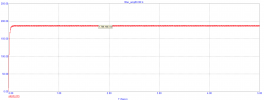
The simulations are right there. They give you everything you need to know about what MUST happen to the DC voltage IF YOU FILTER.

")