
Sythrix
Senior Member
- Joined
- Mar 8, 2018
- Messages
- 331
- Likes
- 264
I have decided to build the WHAMMY DIY Headphone amp, as it looks fairly straightforward. I got interested in the project after finding the PCB on the diyAudio store. The build guide is a little bare-bones in some aspects, but there's schematics, pictures and it's detailed enough that you can get through without too much trouble. What's unfortunate is that there are some items, like the volume knob, RCA L & R inputs, and a few other things that simply aren't listed in the BOM. Also, there's a small amount of drilling and cutting that needs to go on here, for the holes and the IEC inlet. I have already talked to my uncle, who has a drill press and the know-how to help me out with those aspects, so when I finish the PCB, I'll go to his house and finish up the case and anything else.
If you want access to my project on Mouser, let me know and I will send you the link, however I make no guarantee of its completeness. You need to crosscheck what you're going to do with what is on the BOM... for instance, I still don't know if the capacitor he coupled to safety ground was on the BOM or if that's just something I need to discover myself. Besides Mouser, I ordered the transformer from Digi-Key and the RCA inputs from Performance Audio (Left and Right). Performance Audio also has really good prices on some of their bulk cable, which is where I got mine for this project as well as the cables I'll be making in a couple months or so.
(All photos taken with a Sony α65 and a Sigma 70mm F/2.8 EX DG Macro lens, except the first, which was taken with the Sony DT 18-135mm lens).

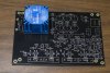
I had attached the Transformer and wired the voltage before beginning documentation of this experience.

Closer shot.

Rear of the PCB


The build guide calls for assembling the power supply portion first, in order to test it, so I've laid out the smallest components for soldering.
 ...and here we see a group of happy little leads...

...and now they'll be happy as future bridges or whatnot. (PCB has not been cleaned yet).

Now I'm working my way up to the taller components. There's actually a lot of room on this PCB so i'm not too worried about future soldering of the main circuit.

I was worried about not having any nuts for the opposite side, but it turns out I have a bunch of screws that are the perfect size to create their own threads in the heatsinks, so problem solved! I'm using some of the TIM I used on one of my old video cards, from when I changed out the paste.

Ready to go! (EDIT: Forgot to mention I changed to slightly smaller headed screws, because the initial ones were too wide).


That's it for now. I'll upload more as I finish. I hope to have the main board done this week, with the case being drilled out next week along with final completion.
Let me know if you have any questions or if you want to point out a concern. We're all prone to miss something now and again.
Also, if you're doing anything like this yourself, don't hesitate to speak as I'd love to hear about it!
Until next time.
If you want access to my project on Mouser, let me know and I will send you the link, however I make no guarantee of its completeness. You need to crosscheck what you're going to do with what is on the BOM... for instance, I still don't know if the capacitor he coupled to safety ground was on the BOM or if that's just something I need to discover myself. Besides Mouser, I ordered the transformer from Digi-Key and the RCA inputs from Performance Audio (Left and Right). Performance Audio also has really good prices on some of their bulk cable, which is where I got mine for this project as well as the cables I'll be making in a couple months or so.
(All photos taken with a Sony α65 and a Sigma 70mm F/2.8 EX DG Macro lens, except the first, which was taken with the Sony DT 18-135mm lens).
I had attached the Transformer and wired the voltage before beginning documentation of this experience.
Closer shot.
Rear of the PCB
The build guide calls for assembling the power supply portion first, in order to test it, so I've laid out the smallest components for soldering.
...and now they'll be happy as future bridges or whatnot. (PCB has not been cleaned yet).
Now I'm working my way up to the taller components. There's actually a lot of room on this PCB so i'm not too worried about future soldering of the main circuit.
I was worried about not having any nuts for the opposite side, but it turns out I have a bunch of screws that are the perfect size to create their own threads in the heatsinks, so problem solved! I'm using some of the TIM I used on one of my old video cards, from when I changed out the paste.
Ready to go! (EDIT: Forgot to mention I changed to slightly smaller headed screws, because the initial ones were too wide).
That's it for now. I'll upload more as I finish. I hope to have the main board done this week, with the case being drilled out next week along with final completion.
Let me know if you have any questions or if you want to point out a concern. We're all prone to miss something now and again.
Also, if you're doing anything like this yourself, don't hesitate to speak as I'd love to hear about it!
Until next time.
Attachments
Last edited:

")
