That is what I intended to convey.This picture is not from PA7/7+, its PA5 (before and after) with a different cooling done by a FM himself.

-
WANTED: Happy members who like to discuss audio and other topics related to our interest. Desire to learn and share knowledge of science required. There are many reviews of audio hardware and expert members to help answer your questions. Click here to have your audio equipment measured for free!
- Forums
- Audio, Audio, Audio!
- Amplifiers, Phono preamp, and Analog Audio Review
- Stereo and Multichannel Amplifier Reviews
You are using an out of date browser. It may not display this or other websites correctly.
You should upgrade or use an alternative browser.
You should upgrade or use an alternative browser.
Topping PA5 Review (Amplifier)
- Thread starter amirm
- Start date
- Joined
- Dec 17, 2021
- Messages
- 649
- Likes
- 1,422
I can't speak for that user, but for my own PA5 I decided removing the molded casing over the op amps is more risky than I care for (i.e. breakage).Why not remove that protective casing and allow better cooling of the element underneath?
For heat mitigation, I drilled 10 holes over the molded part in question, and it runs noticeably cooler. I also have a 25x50x10mm heat sink on the way that'll show up in the mail any day now. I intend to put the heatsink on the molded piece, same as the photo that was posted earlier. Between the heatsink and the holes above it, I'm hoping that works. If it ends up failing anyway, then a Buckeye amp is in my future.
Last edited:
Grooved
Addicted to Fun and Learning
- Joined
- Feb 26, 2021
- Messages
- 682
- Likes
- 441
For heat mitigation, I drilled 10 holes over the molded part in question, and it runs noticeably cooler. I also have a 25x50x10mm heat sink on the way that'll show up in the mail any day now. I intend to put the heatsink on the molded piece, same as the photo that was posted earlier...
I'm betting that the 10 holes will have a better impact than putting an heatsink on the module.
As it is built, the module is certainly transferring heat on all its sides, and not just from the top, so a heatsink on the top only might not be very efficient.
The board (inside the module) has two opamps on its top and two opamps on its bottom, so to get the most efficient system, you need to transfer heat from both sides of the board. Ideally, it would be a copper heatsink covering the two top opamps, and one copper plate on the bottom ones with a heatpipe from there going to the top through the heatsink.
If there was only one row of pins, the easiest way would have been some kind of U shape copper plate making contact with the four opamps, and heatsink on plate (top side). And holes in the amp case to let that heat go out
If only the four opamps were on the top side, it would have been very easy, just putting a copper heatsink on that (and still holes on the top of the case)
- Joined
- Dec 17, 2021
- Messages
- 649
- Likes
- 1,422
Interesting! Looks like I'll be drilling the same holes in the bottom of the case also to let it draw in cool air. Thanks for pointing this out.I'm betting that the 10 holes will have a better impact than putting an heatsink on the module.
As it is built, the module is certainly transferring heat on all its sides, and not just from the top, so a heatsink on the top only might not be very efficient.
The board (inside the module) has two opamps on its top and two opamps on its bottom, so to get the most efficient system, you need to transfer heat from both sides of the board. Ideally, it would be a copper heatsink covering the two top opamps, and one copper plate on the bottom ones with a heatpipe from there going to the top through the heatsink.
If there was only one row of pins, the easiest way would have been some kind of U shape copper plate making contact with the four opamps, and heatsink on plate (top side). And holes in the amp case to let that heat go out
If only the four opamps were on the top side, it would have been very easy, just putting a copper heatsink on that (and still holes on the top of the case)
Last edited:
Grooved
Addicted to Fun and Learning
- Joined
- Feb 26, 2021
- Messages
- 682
- Likes
- 441
Yes, exactly what I wanted to add in my post, as it will create a natural flow.Interesting! Looks like I'll be drilling the same holes in the bottom of the case also to let it draw in cool air. Thanks for pointing this out.
If you have an infrared thermometer, try to first measure the temp of the module through your top holes, then drill the bottom ones and let run the amp in the same conditions and measure the new temp, still from the top holes
If it's still not low enough, the only thing would be to tear down the module, then I would go with the U shape copper plate (cut in the middle because of the pins row, and thermal pad/paste between opamps and copper plate) and heatsink on top like bellow
(I already create ones for other projects and it works great for boards with chips on both sides, not as good than with a heatpipe from bottom to top, but still a great improvement)
Last edited:
gamerpaddy
Member
Again, its not just the heat.
those chips dont get this warm to harm themselves. even in an enclosed space without venting holes.
its the potting compoung expanding and contracting when thermal cycling that seems to rip solder pads apart.
The best way to prevent thermal cycling would be to leave the amp running all the time or just removing the compound entirely.
since i removed it and fixed the solder joints, my pa5 is running as if it was brand new, for longer than it ever has been.
best way to remove it is with a lot of heat and care.
heat to 250..300C using a heatgun, and carefully scrape away the epoxy in chunks one by one. takes an hour or two and you may rip something off the board...
Because of that hassle,
im working on a replacement d01 module right now
for everyone to fix and make their pa5 live longer.. now that its discontinued
As im on a tight budget, im glad a kind ASR user donated me a PA5 for this purpose. thanks again.
its in its testing stage, parts are still missing.
When its ready, i wont sell them by myself, but i wouldnt say no to any donation
You can order the assembled PCB's on the usual chinese pcb websites or solder them by yourself.
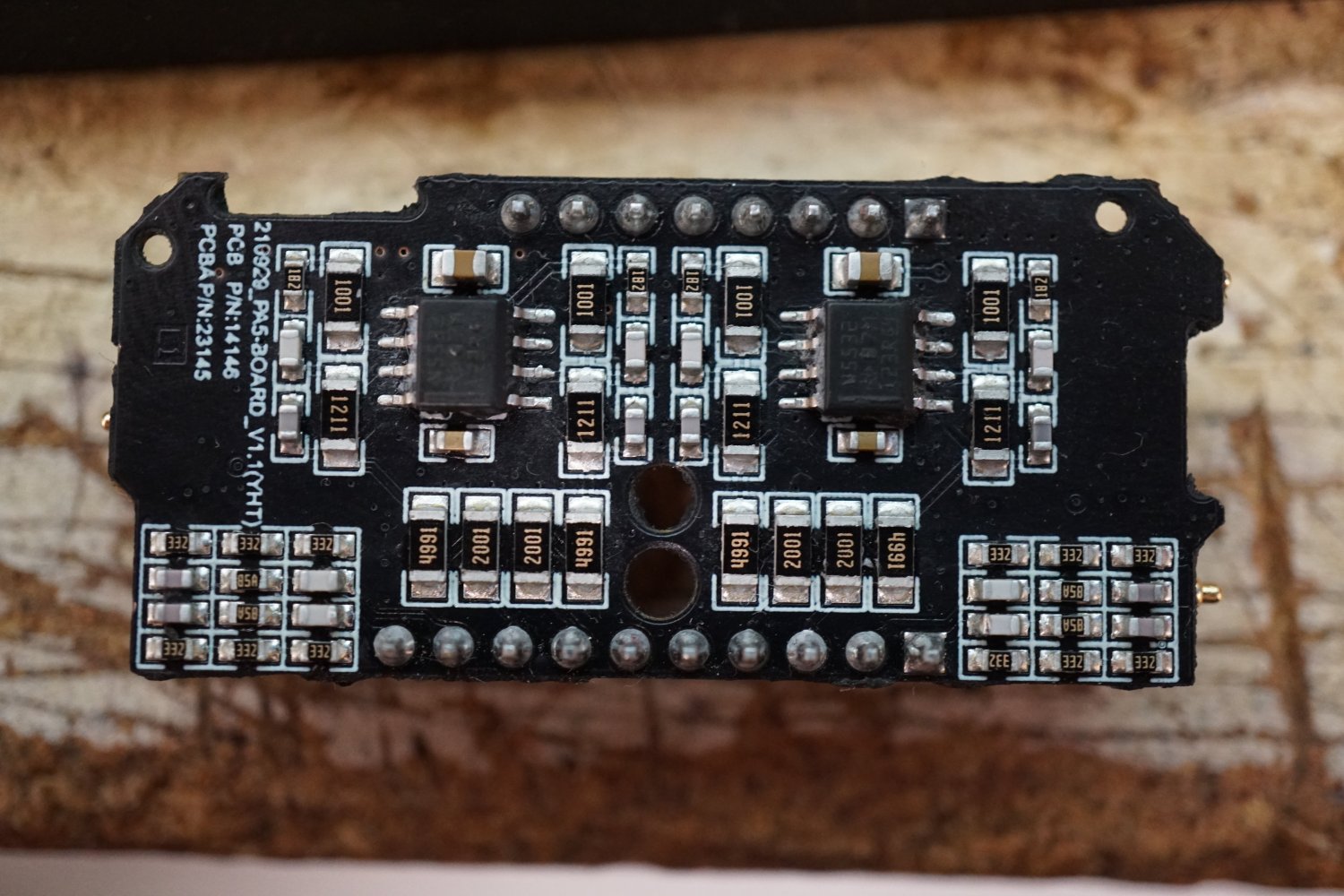
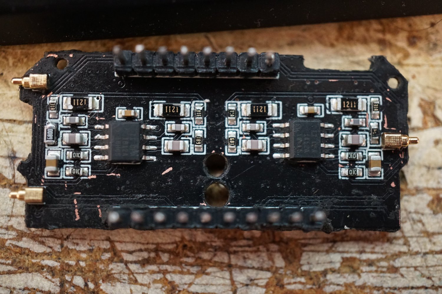
I sanded down the D01 4 layer pcb to see where stuff is going and measured all parts.


ive drawn a schematic and made some PCB's, and i will release it when im 100% sure it works properly.
I cant measure SINAD tho, dont have a APx. But since its using the same parts, it shouldnt differ much.
i want to make different versions of it, like for those people who want to do opamp swapping with dip8 sockets.

its missing the bottom side parts still, since they didnt have opa1612 in stock at that time.
I will post an update soon with more details.
those chips dont get this warm to harm themselves. even in an enclosed space without venting holes.
its the potting compoung expanding and contracting when thermal cycling that seems to rip solder pads apart.
The best way to prevent thermal cycling would be to leave the amp running all the time or just removing the compound entirely.
since i removed it and fixed the solder joints, my pa5 is running as if it was brand new, for longer than it ever has been.
best way to remove it is with a lot of heat and care.
heat to 250..300C using a heatgun, and carefully scrape away the epoxy in chunks one by one. takes an hour or two and you may rip something off the board...
Because of that hassle,
im working on a replacement d01 module right now
for everyone to fix and make their pa5 live longer.. now that its discontinued
As im on a tight budget, im glad a kind ASR user donated me a PA5 for this purpose. thanks again.
its in its testing stage, parts are still missing.
When its ready, i wont sell them by myself, but i wouldnt say no to any donation
You can order the assembled PCB's on the usual chinese pcb websites or solder them by yourself.
I sanded down the D01 4 layer pcb to see where stuff is going and measured all parts.
ive drawn a schematic and made some PCB's, and i will release it when im 100% sure it works properly.
I cant measure SINAD tho, dont have a APx. But since its using the same parts, it shouldnt differ much.
i want to make different versions of it, like for those people who want to do opamp swapping with dip8 sockets.
its missing the bottom side parts still, since they didnt have opa1612 in stock at that time.
I will post an update soon with more details.
Martinvb
Active Member
Respect!Again, its not just the heat.
those chips dont get this warm to harm themselves. even in an enclosed space without venting holes.
its the potting compoung expanding and contracting when thermal cycling that seems to rip solder pads apart.
The best way to prevent thermal cycling would be to leave the amp running all the time or just removing the compound entirely.
since i removed it and fixed the solder joints, my pa5 is running as if it was brand new, for longer than it ever has been.
best way to remove it is with a lot of heat and care.
heat to 250..300C using a heatgun, and carefully scrape away the epoxy in chunks one by one. takes an hour or two and you may rip something off the board...
Because of that hassle,
im working on a replacement d01 module right now
for everyone to fix and make their pa5 live longer.. now that its discontinued
As im on a tight budget, im glad a kind ASR user donated me a PA5 for this purpose. thanks again.
its in its testing stage, parts are still missing.
When its ready, i wont sell them by myself, but i wouldnt say no to any donation
You can order the assembled PCB's on the usual chinese pcb websites or solder them by yourself.
I sanded down the D01 4 layer pcb to see where stuff is going and measured all parts.
View attachment 280601View attachment 280602View attachment 280603View attachment 280604
ive drawn a schematic and made some PCB's, and i will release it when im 100% sure it works properly.
I cant measure SINAD tho, dont have a APx. But since its using the same parts, it shouldnt differ much.
i want to make different versions of it, like for those people who want to do opamp swapping with dip8 sockets.
View attachment 280605
its missing the bottom side parts still, since they didnt have opa1612 in stock at that time.
I will post an update soon with more details.
Again, its not just the heat.
those chips dont get this warm to harm themselves. even in an enclosed space without venting holes.
its the potting compoung expanding and contracting when thermal cycling that seems to rip solder pads apart.
The best way to prevent thermal cycling would be to leave the amp running all the time or just removing the compound entirely.
since i removed it and fixed the solder joints, my pa5 is running as if it was brand new, for longer than it ever has been.
best way to remove it is with a lot of heat and care.
heat to 250..300C using a heatgun, and carefully scrape away the epoxy in chunks one by one. takes an hour or two and you may rip something off the board...
Because of that hassle,
im working on a replacement d01 module right now
for everyone to fix and make their pa5 live longer.. now that its discontinued
As im on a tight budget, im glad a kind ASR user donated me a PA5 for this purpose. thanks again.
its in its testing stage, parts are still missing.
When its ready, i wont sell them by myself, but i wouldnt say no to any donation
You can order the assembled PCB's on the usual chinese pcb websites or solder them by yourself.
I sanded down the D01 4 layer pcb to see where stuff is going and measured all parts.
View attachment 280601View attachment 280602View attachment 280603View attachment 280604
ive drawn a schematic and made some PCB's, and i will release it when im 100% sure it works properly.
I cant measure SINAD tho, dont have a APx. But since its using the same parts, it shouldnt differ much.
i want to make different versions of it, like for those people who want to do opamp swapping with dip8 sockets.
View attachment 280605
its missing the bottom side parts still, since they didnt have opa1612 in stock at that time.
I will post an update soon with more details.
Very, very cool. Awesome work.
Michael
Grooved
Addicted to Fun and Learning
- Joined
- Feb 26, 2021
- Messages
- 682
- Likes
- 441
Thanks, missed this information in the thread, but it seems to make sense because these opamps are not supposed to need any heatsink to work correctly and not for some weeks/months onlyAgain, its not just the heat.
those chips dont get this warm to harm themselves. even in an enclosed space without venting holes.
its the potting compoung expanding and contracting when thermal cycling that seems to rip solder pads apart.
I don't understand the initial design choice of this module
Anyway, nice job with these boards!
KintsugiUwU
Member
- Joined
- Apr 26, 2023
- Messages
- 8
- Likes
- 3
Never had an issue but it runs warm, last summer I had to use a fan to blow air in the back holes.
Today I asked for a refund tho, not gonna risk it breaking while warranty expired and loosing 350€. As much as I love this thing, I can’t risk it.
Do you have any suggestions for a replacement? Maybe the smsl AO200?
Today I asked for a refund tho, not gonna risk it breaking while warranty expired and loosing 350€. As much as I love this thing, I can’t risk it.
Do you have any suggestions for a replacement? Maybe the smsl AO200?
Last edited:
KintsugiUwU
Member
- Joined
- Apr 26, 2023
- Messages
- 8
- Likes
- 3
May you send a picture of the vents on the back?Oh makes sense. I have a vented unit (those small openings at the back?).
Also I am placing a metal XLR routing switch on top of it as a free makeshift heatsink.
KintsugiUwU
Member
- Joined
- Apr 26, 2023
- Messages
- 8
- Likes
- 3
Ok, today the Aiyima T9 Pro arrived, and running it for about an hour I can say that the both get the same warmth. Tho the T9P uses a 32V PSU whereas the Topping uses a 38V PSU. Edit: ok the T9P is warmer than the PA5, so I assume my unit is not from the bad batch.
My Topping PA5 number is 2201126025 ordered on the 3rd of April 2022. Been running 10-12h a day every day.
My Topping PA5 number is 2201126025 ordered on the 3rd of April 2022. Been running 10-12h a day every day.
Last edited:
gamerpaddy
Member
i finished the modules to fix broken PA5's
 www.audiosciencereview.com
Topping PA5 fix - D01 Module Replacement for everyone
Ive been working on the PA5 for a while now after mine died suddently, like many others https://www.audiosciencereview.com/forum/index.php?threads/poll-for-topping-pa5-owners-only-please.33293/ Most of the PA5 units develop a crackling, hissing or just go a little silent or completely dead on...
www.audiosciencereview.com
Lräk
Member
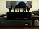
Instead of drilling holes in the case, I replaced the bottom pads with these 3/4 inch feet. I figured the vents in the bottom weren't getting enough air. After 2 hours of using my PA5 at a decent volume, the case was still cold to the touch. Easy to remove the old feet with a butter knife.
Attachments
It seems that the PA5 ll Plus will be released soon, but I can't wait to announce the details of how it has evolved.
Attachments

It seems that the PA5 ll Plus will be released soon, but I can't wait to announce the details of how it has evolved.
I’m looking forward to this, I’ve built a new pair of desktop monitors and amps with the power, size, and distortion of PA5 with enhanced reliability would be perfect.
Lräk
Member
It would be hilarious if they just used @gamerpaddy redesigned D01 module:It seems that the PA5 ll Plus will be released soon, but I can't wait to announce the details of how it has evolved.
Topping PA5 fix - D01 Module Replacement for everyone
Ive been working on the PA5 for a while now after mine died suddently, like many others https://www.audiosciencereview.com/forum/index.php?threads/poll-for-topping-pa5-owners-only-please.33293/ Most of the PA5 units develop a crackling, hissing or just go a little silent or completely dead on...
www.audiosciencereview.com
Similar threads
- Replies
- 59
- Views
- 8K
- Poll
- Replies
- 891
- Views
- 181K
- Replies
- 15
- Views
- 980
- Replies
- 25
- Views
- 5K
- Replies
- 1K
- Views
- 184K