So, how come that the panel gets into a secondary mode, while the force is uniform?!
(citation from above link, only for scientific discussion ;-)
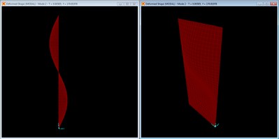
The force is mathematically uniform, point symmetrical, right?! No, that force wasn't considered atall when generating the image--it shows a possible motion of the panel, but not the concrete reaction to any force that may be applied by the internal air. Period. The picture presents an Eigen-mode, a singular building block of more complicated patterns that may (or not) comprise the 1st, 3rd etc mode also.
Such kind of a 'fundamental' analysis is always seen, but I never saw a really fundamental analysis that necessarily has to include the driving force for the (desired?!) panel movement.
Please think Yourselves. Some posts above I gave You otherwise quite costly data that I generated in private, while being, by the papers, a full fleshed scientist. My observations are true. What I didn't consider to be necessary to mention is that model I once set up using the old Akabak. Same result: forget about the eiigenmodes of the panels, but concentrate on the internal air column resonances.
You are willing to think yourselves. Just do it! How come?
")