• WANTED: Happy members who like to discuss audio and other topics related to our interest. Desire to learn and share knowledge of science required. There are many reviews of audio hardware and expert members to help answer your questions. Click here to have your audio equipment measured for free!

Second opinion on my measurements

neRok

Senior Member
Joined
Oct 7, 2022
Messages
304
Likes
175
Location
Australia
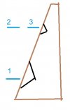
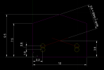
I just drew up your room in CAD and a 50Hz reflection node seems to be bang on with both the LP and the speakers passive radiator. That's a double null whammy lol.
ceiling2.png

The "node" is the null point of a reflection. All frequencies have an anti-node (boost) at the reflecting surface, and a node (null) at a distance of 1/4 wavelength from the surface. Room modes are when these stack together evenly. And there is often a prominent dip from a node caused by the back wall.
waves(right).jpg

The "double whammy" is because you are both listening on a node whilst the passive radiators are playing on a node (when something plays on a node, it cancels itself, like shown in the Visualisation thread I linked at the start). If you can change one aspect, you should be able to improve the null a bit. If you move the speakers close to the walls, the walls might help "shade" the ceiling from the speaker.

If you get a sub, it won't play on to the same node, but you will still be sitting in the same node.

Edit: If you could upload the measurement mdat for 1 speaker at the main LP, I've got some ideas I would like to test.
 
Last edited:

dominikz

Addicted to Fun and Learning
Forum Donor
Joined
Oct 10, 2020
Messages
806
Likes
2,638
Floor to higest point : 9.5 ft
Floor to lowest point: 7.5 ft
Length: 16 ft
Width: 12 ft
Center of the speaker to the side wall: 2.2 ft
Primary listening position to the front wall: 12.8 ft
Primary listening position to the speaker mid/tweet: 8 ft
Top of the speaker to the ceiling: 4.4 ft
Woofer (center) to the floor: 1.6 ft
Passive (center) to the floor: 2.4

@dominikz : The woofer is 1.6 ft from the floor and passive is 2.4ft from the floor, also the woofer plays upto 500hz.
Dialling in the dimensions you provided into an online SBIR calculator gives the following result:
1693556058206.png

The front-wall (wall behind loudspeakers) boundary interference first null frequency seems to coincide with your dip. Ceiling reflection could be a cause as well, but that is more difficult to estimate due to the vaulted shape of the ceiling. As mentioned before, I suspect that pushing the loudspeaker back towards the wall would bring the dip up in frequency.
If you can bring them close to the back wall, perhaps you could even get the dip to a high enough frequency to use porous absorbers to attenuate the backwall reflection to reduce the dip.
But IMHO a better solution would probably be to keep your loudspeaker where they are, high-pass them at ~80Hz and use subwoofers placed near back walls (or even in corners for least SBIR nulls and most headroom) to reproduce <80Hz content. As @radix suggested, you could use any full-range loudspeaker to experiment with this before buying subs. Then use room EQ to bring down peaks in the bass.

Hope this helps and good luck!
 
OP
P

pollock0424

Active Member
Joined
Jun 30, 2022
Messages
125
Likes
55
Cool. It looks pretty weak because usually there are more strong waves (3 up and 3 down on the % plot seems to be "good"), but I don't have a big sample size of "good". The first reflections arrive very quickly (lets say its 3m up and 3m down, that's 17msec travel), and so it can still be the ceiling. Maybe its that you are actually in the node of the ceilings reflection?!

Could you also post a filtered IR of 100Hz (a frequency that appears good), and a screenshot of the Decay tab with "Fill Slices" off, and smooth=1/24 (make sure you turn off the filtered IR first)?
Here are the plots for FIR@100hz and Decay@1/24th:
FIR_13rd_100hz_thiel36_right_mlp.jpg


decay_124th_thiel36_right_mlp.jpg
 

Attachments

  • decay_124th_thiel36_right_mlp.jpg
    decay_124th_thiel36_right_mlp.jpg
    170.2 KB · Views: 35

neRok

Senior Member
Joined
Oct 7, 2022
Messages
304
Likes
175
Location
Australia
@neRok : Here's the right speaker measurement from the primary LP. Thiel36_RSp_MLp
Is this the same measurement as the filtered IR you shared in post #18? Because mine looks different. If it isn't the same, then what's the difference between the measurements? Because that might give clues about what is happening at 50Hz (and hence why the Filtered IR looks different). Or it might just be a difference with our REW versions, but that doesn't make sense (a bandpass is a bandpass).

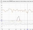
I think there is 2 problems on top of each other in the 50-60Hz range. The decay plot suggests as much;
decay.jpg

If it's a wall based reflection problem, then moving the speaker forward/back in the room should show some change (move the frequency anomaly). But if that doesn't move the freq of these problems, then it suggests the problem is ceiling based. You won't know until you do some more tests with different speaker positions.

One other thing, I was looking at your distortion plot, and there is a problem around 350Hz. You should probably try track it down and fix it.
dist.jpg

Actually, a bonus thing: the specs of your speakers say 500Hz crossover woofer to mid, but there is a bit of null nearby at 550-600Hz. Maybe the drivers aren't crossed the best (one might need delaying), and this is where they are having phase problems? You could test/verify by using an acoustic ref and measuring with the mic right up close to each driver (so 2 measures). That should reveal any timing problem. If there was a problem, I don't think there's anything simple you could do with what you have, so it's probably just more of an academic exercise.
 

ozzy9832001

Senior Member
Joined
Feb 19, 2023
Messages
405
Likes
257
help2.jpg


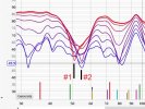
If you look at the spectrogram, you can see issues at 50-60 hz and 80-100. In addition to that, the entire spectrum up to about 2k has a lot of issues. Most of this is caused by an excitable, highly reflective room.

The best bet to fix some of these issues is to put the speakers much closer to the front wall. This will eliminate it as a surface for interference and push any SBIR up to a more treatable range.

The deep nulls in the bass will either require treatment, a subwoofer or 2, speaker and MLP repositioning or a combination of all of them. The best thing would be to try and find a position where he is only dealing with one null, rather than a series of them. I would personally try setting up along the 16' wall, and not the 12, and see how that goes.

Also, the foam wedges show in the picture won't do anything for absorption. They'll mostly cause reflections.

The issue at 350hz is probably something running in the background like an AC/HVAC or someone flushed the toilet.
 
OP
P

pollock0424

Active Member
Joined
Jun 30, 2022
Messages
125
Likes
55
@neRok :
Good news! I tried a couple different locations and I think it sounds significantly better. I sent Rigt speaker measurement from the MLP, I might have used left speaker to post here. However, I will send some more measurements for the following setup. MLP hasn't changed just the speakers moved slightly. Best_bass_but_ok_soundstage, 2nd_best_bass_but_good_soundstage

In the best bass configuration speakers are 2.7ft from side wall when measured from the center of the speaker and 4.3 ft from the back wall when measured from the baffle at the widest portion of the speaker (near the bottom woofer). Initially it was 5.5ft from the wall behind the speaker.

In the 2nd best bass config speakers are 2.1 ft from side wall and 4.1ft from the wall behind the speaker. I chose this config as my main location based on listening to some of the tracks that I'm used to.

Below are the plots for the best bass config.

Here's the FR @1/12th (Solid line is the average response)
FR_20hz_200hz_best_bass.jpg

200Hz to 20khz @ 1/6th

FR_200hz_20khz_best_bass.jpg


Here are distortion plots: (Left speaker)
distortion_left_best_bass.jpg


Right speaker:
distortion_right_best_bass.jpg


I will further invesstigate this weird distortion hump in the right speaker.

@ozzy9832001 : I made sure that AC was turned off but the fan could be still running on the outside unit. How is your spectrogram different when compared to this ?

Spectrogram_right_best_bass.jpg


And the RT60 Decay:

RT60_decay_right_best_bass.jpg
 

ozzy9832001

Senior Member
Joined
Feb 19, 2023
Messages
405
Likes
257
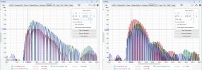
When looking at the spectrogram in frontier it is showing the frequencies in relation to each other. What I posted was Burst Decay which is based on cycle length. For yours it's about a 1 cycle delay from 50-60hz and the same at 80-100. The sound is heard, just not when it should be. The graph is easier to read normalized.

This is yours normalized:

normal.jpg
 
OP
P

pollock0424

Active Member
Joined
Jun 30, 2022
Messages
125
Likes
55
When looking at the spectrogram in frontier it is showing the frequencies in relation to each other. What I posted was Burst Decay which is based on cycle length. For yours it's about a 1 cycle delay from 50-60hz and the same at 80-100. The sound is heard, just not when it should be. The graph is easier to read normalized.

This is yours normalized:

View attachment 309286
Do you have an example for a perfect or very good plot for this?
 

neRok

Senior Member
Joined
Oct 7, 2022
Messages
304
Likes
175
Location
Australia
In the best bass configuration speakers are 2.7ft from side wall when measured from the center of the speaker and 4.3 ft from the back wall when measured from the baffle at the widest portion of the speaker (near the bottom woofer). Initially it was 5.5ft from the wall behind the speaker.

In the 2nd best bass config speakers are 2.1 ft from side wall and 4.1ft from the wall behind the speaker. I chose this config as my main location based on listening to some of the tracks that I'm used to.
Ah nice one. This suggests it is the wall reflections dominating, which is good (better than it being the ceiling). Actually your "new best" config seemed quite good in that 50-60Hz range because it managed to regain SPL and resolve the GD blips;
new.jpg

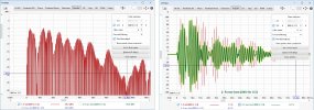
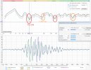
So like dominikz post showed with the SBIR calculator, it must be the front wall SBIR issue. And if you moved the speakers closer to the front wall, then the frequency would have increased (high freq = shorter length). So comparing the filtered IR's, you can see that in the old position that response was being cancelled after ~34ms, but in the new positions 50Hz looks good. But because you've moved the problem, I think it starts to appear on 63Hz plot. Still it seems better than it was.
new2.jpg

800Hz on your old measure had me wondering if it was the crossover too (drivers not time aligned), just like I wondered at 550-600Hz. The specs I saw for your speakers suggested 1st order filters, which means the woofer is only ~-5dB at 800Hz. If it wasn't time aligned with the mid woofer, you would expect lots of distinct peaks, and that's actually what there was. But moving it has reduced those duplicate peaks, so maybe it's just wall reflections. Without measuring close up, it's all just conjecture.
new3.jpg
 
OP
P

pollock0424

Active Member
Joined
Jun 30, 2022
Messages
125
Likes
55
@neRok
Thanks, I will further investigate based on your inputs. This speakers have a slanted baffle meant to physically align the drivers. Also, if I want to measure the speaker up close then which driver should I be measuring?

Here's a "technical" bulletin for this model.
 

neRok

Senior Member
Joined
Oct 7, 2022
Messages
304
Likes
175
Location
Australia
Thanks, I will further investigate based on your inputs. This speakers have a slanted baffle meant to physically align the drivers. Also, if I want to measure the speaker up close then which driver should I be measuring?
You may as well cover all bases. So measure the woofer up close, then move the mic straight up to measure the mid, and then a 3rd measure with the mic close to the mid.
mic.jpg
 
OP
P

pollock0424

Active Member
Joined
Jun 30, 2022
Messages
125
Likes
55
You may as well cover all bases. So measure the woofer up close, then move the mic straight up to measure the mid, and then a 3rd measure with the mic close to the mid.
View attachment 309309
Okay, I am headed out to vacation and will be back next Friday. I will post the measurements in this thread once I'm done.
Looking forward to seeing them! Also, is there a way to time gate the measurements to ignore reflections? I'm assuming that distance /speed of sound in air should approximately give me that window? Or am I being inexperienced in thinking like this?
 

neRok

Senior Member
Joined
Oct 7, 2022
Messages
304
Likes
175
Location
Australia
Okay, I am headed out to vacation and will be back next Friday. I will post the measurements in this thread once I'm done.
Looking forward to seeing them! Also, is there a way to time gate the measurements to ignore reflections? I'm assuming that distance /speed of sound in air should approximately give me that window? Or am I being inexperienced in thinking like this?
You can change the IR windows in REW, which is what you are talking about. There are threads on the topic called "quasi-anechoic method". But it is not effective at low frequencies because they are so long in time that the reflections start arriving before a full cycle tone has played. But by measuring up close, it should mean the speakers sound will dominate the measure, and any time differences should be obvious because the direct waves arriving at the mic are the first thing to happen.
 
OP
P

pollock0424

Active Member
Joined
Jun 30, 2022
Messages
125
Likes
55
@neRok : Got some time today so I did the measurements, however, I was unable to do any analysis. Looking forward to some time next week. Here's the link for measurements, if you're interested in taking a look. The version that has UpClose name was collected very closely, 3 to 4 inches distance. Notes in the measurements should be self sufficient.

I also inlcluded the measuremnts for the newer slightly better compromise between bass and soundstage position. Spectrograms definitely show the regions where each of the driver is supposed to work.
 
Last edited:

neRok

Senior Member
Joined
Oct 7, 2022
Messages
304
Likes
175
Location
Australia
I took a quick look. A good thing to do/check when you do your individual left and right measures, then stereo measure, is to keep the mic in the same spot. Then in REW do left+right arithmetic (A plus B, or via alignment tool), and the sum should roughly match the stereo measure (which is a good sanity check). Then check areas where the sum cancels (dips below the original measures). With the measures you took (which the notes suggest were slightly different positions), there seems to 2 bad cancellations, and 2 nearly-cancels. Like at 88Hz indicated, it seems the right speaker has some reflections cancelling its its early waves, and so it has strong late-waves (excess phase waves). You might try tweaking the position slightly, or solving the reflection problem, or maybe even trying EQ/allpass on one speaker to induce further phase shift in the problem frequency - the end goal being to not lose SPL with the sum.
sum.jpg

About your individual driver sweeps, did you use acoustic ref? I saw on one of the woofer sweeps that there was substantlial sound before the t=0, so maybe that was the ref noise? I haven't tested if that affects the results (if you don't window it out)? Maybe try use the opposite speaker as the ref source? Maybe also sweep drivers closer to their range only, so woofer 0-2kHz, tweeter 1kHz-20kHz, etc.

Unfortunately I'm not in the mood to deeply consider what's going on with the rest of the system. A couple of quick comments;
  • The woofer SPL and GD looks alright
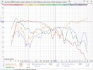
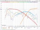
  • I'm not sure about the passive woofer. I thought they functioned like ports, so mostly functioned at the lowest frequencies? But it seems to make lots of sound >600Hz, especially at the peaks I numbered. I wonder if the back-side output of the mid driver is coming out through the passive woofer or something?
  • The mid driver runs much quieter than the woofer and tweeter. Maybe the "sums" work out fine, but it seems a little odd. Maybe the "noise" from the passive woofer is part of the design?
  • The tweeter above 2kHz looks fine, but why it rises in SPL at 700Hz is a bit strange. Maybe just the other drivers getting captured by the mic?
drivers.jpg sum.jpg
 

Attachments

  • drivers2.jpg
    drivers2.jpg
    413.6 KB · Views: 63
OP
P

pollock0424

Active Member
Joined
Jun 30, 2022
Messages
125
Likes
55
@neRok :I appreciate your comments and insights so far. From this reply of yours I will concentrate on two items.

1. "Then check areas where the sum cancels (dips below the original measures)." - I will tweak position of the speakers so that there are no major cancellations going on. What do you mean by "trying EQ/allpass" ? Pardon me, I am not aware of this. Does this induce some kinda phase delay in one speaker for only certain frequencies thus reducing the cancellations ? If yes, then does that have any negative effects on the sound stage ? All pass filters typically introduce phase shifts but over all the frequencies and the magnitude of phase shift varies with frequency.

2. "the end goal being to not lose SPL with the sum.", This is enlightening for sure, I will use the sanity check that you proposed! Hmm.. I didn't even verify! I thought of cancellations happening between two channels but didn't take action about it!


I'm not sure what an acoustic ref is.

In this speakers, mids and tweeters are firing into their own sealed chambers that have about 1 inch thick walls. It is not likely that the passive is picking up the back wave from the mid. May be the mic picked it from the front.

My next iteration is to measure the drivers approximately swept in their domains. Once again, thanks for your patience! This will give me a good starting point.
 

neRok

Senior Member
Joined
Oct 7, 2022
Messages
304
Likes
175
Location
Australia
I'm not sure what an acoustic ref is.
On REW's "Make a measurement" screen you can choose a timing ref. To properly time align different measurements you need to use a fixed/common timing ref, which an acoustic ref can achieve (it makes a little chirp before and after the sweep, and uses that to set t=0).

What do you mean by "trying EQ/allpass" ? Pardon me, I am not aware of this.
Open up the EQ screen in REW, then click the "EQ Filters" button up the top, and then you can set your own filters. You can see their effect on the EQ screens Phase/GD plots. Try out different combos, then click "Generate measurement from predicted", to create a measurement with the filters applied (it should be the same as actually applying the DSP filter and doing another sweep). Then you can use the alignment tool to align 1 fixed speaker with other normal speaker.

And yer, allpass phase shifts the frequencies in their area (makes them "late", ie increases GD)

Here's what you have now (I should have written "rights reflections are causing cancellations with itself at the start");
before.jpg
The strong peaks of the right speaker have become out of phase with the left. If you allpass one speaker, you can make the strong-but-late waves of the right speaker become in to phase with the left (but it does mean the early waves will become out of phase).

If you all pass the right, the sum will improve, but the strong peaks are getting very late (maybe so late it will be very smeared or even echoey);
AP right.jpg
Notice the effect of the AP on the EQ phase plot. You can watch this as you try different frequencies/Q's/filter-types/etc.

Instead allpassing the left makes it a little late (compared to where it was), but makes it in phase with right (a case of "two wrongs making a right");
AP left.jpg

You can always compare non-EQ to with-EQ, to see what the allpass is doing;
left vs AP left.jpg

Other possibilities are;
  1. High-Q PK filters that introduce pre-ringing. That might work for the right speaker, because pre-ringing often comes with phase shift, and that might help shift the rights strong+late waves forward in time.
  2. EQ down the right speaker at this frequency so that it doesn't contribute as much (doesn't contribute by causing cancelling).
  3. I'm not sure what a notch filter actually does, but it might be the same as #2.
Maybe a combo of left+AP and right+AP is best?
 
Last edited:
OP
P

pollock0424

Active Member
Joined
Jun 30, 2022
Messages
125
Likes
55
@neRok
I feel silly asking this but I will:

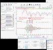
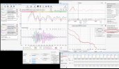
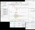
1.How were you able to get the IR (looks like filtered IR ) overlayed along with the "All SPL" plot ?
2. How were you able to visualize the small window that has "Does not have timing reference" written on it ? This window is right below the ALL SPL and Filtered IR plot in your attachments.

Also, I have upgraded to 5.20.14. I understand what you're trying to convey but I just want o replicate it myself locally.
 

neRok

Senior Member
Joined
Oct 7, 2022
Messages
304
Likes
175
Location
Australia
1.How were you able to get the IR (looks like filtered IR ) overlayed along with the "All SPL" plot ?
On the "All SPL" screen, open "Actions", the click the "Alignment tool" and set it to "Impulse alignment" instead of "Phase alignment".

2. How were you able to visualize the small window that has "Does not have timing reference" written on it ? This window is right below the ALL SPL and Filtered IR plot in your attachments.
It's the window for the alignment tool.

Also, I have upgraded to 5.20.14. I understand what you're trying to convey but I just want o replicate it myself locally.
Make sure you have the latest version of REW E.A. from 16 August, as it has bug fixes relating to the alignment tool. https://www.avnirvana.com/threads/v5-20-14-early-access-build.11154/
 
Top Bottom