solderdude
Grand Contributor
Someone tell me that there is no issue with this, and why this issue ought not be addressed.
What issue should be addressed ? The output resistance of 75 ohm (SE) or 600 ohm (Balanced) ? Why would that be an issue ?
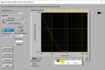
The headphone out circuit design does not seem to work well when loaded with a low impedance load.
So think 50 ohm and lower, it seems to work fine for higher impedance loads like 300 ohm or higher.
As the pre-amp is the same circuit but without the higher power continuity output stage and will only have to drive a few k ohm as the 'heaviest load' it seems to be no problem for the same circuit.
Of course, in passive mode the output impedance will be higher (vary depending on volume setting) which could limit the max. FR when longer or unusually high capacitance interlinks are used. That's where the 'transparent' buffer circuit comes in though which is low enough in output R to drive about any power amp input.
Every passive controller with a volume control will have this issue. Also LDR and transformer coupled ones.