• WANTED: Happy members who like to discuss audio and other topics related to our interest. Desire to learn and share knowledge of science required. There are many reviews of audio hardware and expert members to help answer your questions. Click here to have your audio equipment measured for free!

Right AES/EBU to spdif schematics?

MCH

Major Contributor
Joined
Apr 10, 2021
Messages
2,679
Likes
2,301
Hello, let's see if someone can help me to find the right schematics for AES/EBU inputs/outputs.

What i want to do is to add AES/EBU inputs and outputs to a spdif transceiver chip (wm8805). I thought i could find what i need easily until i found this article, that seems very good but made me realize i am completely lost:


Seems that there are many standards and the paper describes the schematics to convert some of these AES formats to spdif coax, that is not exactly what I need, even though could do if i don't find a more straight forward one.

With this in mind, my question is:
Can someone show me the right schematics for conversion of AES/EBU - the one found in many desktop DACs, some minidsp processors and some active speakers- to spdif directly to the transceiver? Or at least show me which one, if any, is the one from Rane's paper? -note that i need both input and output-
Thanks a lot.
 

KSTR

Major Contributor
Joined
Sep 6, 2018
Messages
2,819
Likes
6,330
Location
Berlin, Germany
AES3 into 8805 : After 1:1 input transformer, terminate the line and divide down before going into the 8805 (with DC-blocking cap). Two resistors.
AES3 from 8805 : simply use the proper output divider (yielding the attenuation and output impedance) before going into the output transformer, or simply a 110R series terminator resistor before the transformer. AC-coupled, again.
 

MaxwellsEq

Major Contributor
Joined
Aug 18, 2020
Messages
1,782
Likes
2,717
The Rane note is correct - some of the bits in the frame mean different things when using AES3 or S/PDIF. Most modern encoder or decoder chips should handle both, but there may be unexpected issues.
 
  • Like
Reactions: MCH
OP
M

MCH

Major Contributor
Joined
Apr 10, 2021
Messages
2,679
Likes
2,301
thank you guys.
@KSTR a couple of additional questions. From what you say, i understand this:

1677926956910.png

regarding the input:
- i understand that the AES3 is 4V (?) and the wm8804 expects 3.3V. Are those values what i should use to calculate the values of the two resistors?
regarding borh input and output:
- what happens to pin 1 of AES3? does it stay unconnected? goes to ground of the wm8805?: in Rane's note they write "ground option", like if it is optional? but recommended??

Sorry for my deep ignorance!
 

KSTR

Major Contributor
Joined
Sep 6, 2018
Messages
2,819
Likes
6,330
Location
Berlin, Germany
WM8804/8805 SPDIF receiver can be programmed to either take 3.3V CMOS levels or use a 0.5Vpp comparator setting. Normally one uses the latter.
This input may or may not take more than 0.5Vpp reliably, quite likely it does and ideally it should work up to the 1.65Vpp max as set by a 3.3V supply voltage.
AES3 max is 7Vpp so your attenuation factor should be 0.236, yielding a 27R:82R divider. This in turn means that the minimum safe input level is now 0.85Vpp (as SPDIF requirement is 0.2Vpp). This obviously violates the spec of 0.2Vpp allowable minimum level of AES3 but probably is not a severe restriction.

For the output, with the 110R in series, voltage will be 1.65Vpp at the receiver. It's a bit below AES3 rated minimum output of 2Vpp but I wouldn't expect any problem in practice as AES3 inputs must work down to 0.2Vpp (same spec as for SPDIF). Our own input does work down to 0.85Vpp so even in this case we have a safety margin of 2x here.

As for pin 1 /cable shield) grounding... a controversial topic for sure. I would at least provide AC-grounding at both ends so the shield is effective at RF but breaks low-frequency ground-loops. Often a R//C combo is used, like 10R/10nF, for a "hybrid" grounding scheme.
 
OP
M

MCH

Major Contributor
Joined
Apr 10, 2021
Messages
2,679
Likes
2,301
WM8804/8805 SPDIF receiver can be programmed to either take 3.3V CMOS levels or use a 0.5Vpp comparator setting. Normally one uses the latter.
This input may or may not take more than 0.5Vpp reliably, quite likely it does and ideally it should work up to the 1.65Vpp max as set by a 3.3V supply voltage.
AES3 max is 7Vpp so your attenuation factor should be 0.236, yielding a 27R:82R divider. This in turn means that the minimum safe input level is now 0.85Vpp (as SPDIF requirement is 0.2Vpp). This obviously violates the spec of 0.2Vpp allowable minimum level of AES3 but probably is not a severe restriction.

For the output, with the 110R in series, voltage will be 1.65Vpp at the receiver. It's a bit below AES3 rated minimum output of 2Vpp but I wouldn't expect any problem in practice as AES3 inputs must work down to 0.2Vpp (same spec as for SPDIF). Our own input does work down to 0.85Vpp so even in this case we have a safety margin of 2x here.

As for pin 1 /cable shield) grounding... a controversial topic for sure. I would at least provide AC-grounding at both ends so the shield is effective at RF but breaks low-frequency ground-loops. Often a R//C combo is used, like 10R/10nF, for a "hybrid" grounding scheme.

Awesome, thanks! there it goes, for posterity
*edit: corrected as per post #11

1677949498547.png
 
Last edited:

sarumbear

Master Contributor
Forum Donor
Joined
Aug 15, 2020
Messages
7,604
Likes
7,325
Location
UK
What i want to do is to add AES/EBU inputs and outputs to a spdif transceiver chip (wm8805). I thought i could find what i need easily until i found this article, that seems very good but made me realize i am completely lost:
I like to point you this section from the article you posted.

Conversion Caution​

You can convert one electrical interface to another with just a few parts, but the protocol used in AES3 and S/PDIF is not exactly the same and that can cause problems. The basic data formats are identical, but there is a bit in the channel status frame that tells which is which, and assigns certain bits different meanings.

This sets the stage for incompatibilities. Many older units are sticklers about what's what in each bit, and even though a given signal faithfully complies with the standard, some equipment will still reject it. Fortunately, many units are flexible and tolerant so simple resistor or transformer converters work. But be warned that a converter that works fine with one unit is no guarantee that it will work fine with all units.

Remember that even though the audio data is the same between AES3 and S/PDIF, they have different subcode formats. AES3 converted to 75-ohm coax is not S/PDIF, and S/PDIF converted to XLR balanced is not AES3. Nor is AES3id 75-ohm BNC the same as 75-ohm RCA S/PDIF -- it may work, but it is not the same. They are still in their native format; just the transmission medium has changed. Going from S/PDIF to AES3 has a higher degree of success than the other way around. AES3 signals often are not recognized as valid by S/PDIF inputs. Whether they will work in your application depends on the equipment chosen.

Therefore the following passive circuits convert only the signal level and impedance, and not other protocol details (e.g., sample rate, consumer/professional status, nor correct any block errors in the data stream).
 
  • Like
Reactions: MCH
OP
M

MCH

Major Contributor
Joined
Apr 10, 2021
Messages
2,679
Likes
2,301
I like to point you this section from the article you posted.
Thank you @sarumbear . @MaxwellsEq pointed that out as well, but nothing that i can solve/is in my hands. This is intended to be an optional/additional output in a board i am drafting. If it works, perfect, if it doesn't, well...
 

sarumbear

Master Contributor
Forum Donor
Joined
Aug 15, 2020
Messages
7,604
Likes
7,325
Location
UK
Thank you @sarumbear . @MaxwellsEq pointed that out as well, but nothing that i can solve/is in my hands. This is intended to be an optional/additional output in a board i am drafting. If it works, perfect, if it doesn't, well...
If that is going to be a design for a new equipment don't you think placing an AES3 output on a device which does not output AES3 correctly not a good idea? Shouldn't the user expect correct AES3 format output when they read the label?
 
OP
M

MCH

Major Contributor
Joined
Apr 10, 2021
Messages
2,679
Likes
2,301
If that is going to be a design for a new equipment don't you think placing an AES3 output on a device which does not output AES3 correctly not a good idea? Shouldn't the user expect correct AES3 format output when they read the label?
the only user will be myself :D

I thought it was evident i am a noob tinkerer. This is just a DIY project and the AES3 output is just an additional option i want to leave there in case one day i want to give it a try, just that, and to learn a bit. Rane's note implies that there are chances that it works though, enough for me to throw in a few resistors and see what happens, that's it. But if one day i do this for a living, i will try to make sure i dont need to go to a forum to ask these things :D
But i like you calling out a potential commercial disaster waiting to happen, thanks for that.

btw, if you are curious, the project is here:


KSTR

Major Contributor
Joined
Sep 6, 2018
Messages
2,819
Likes
6,330
Location
Berlin, Germany
Awesome, thanks! there it goes, for posterity

View attachment 269257
Almost ;-)
- Use the 10R and 10nF in parallel, not in series
- swap XLR pins 2 & 3 for correct polarity

As for the alleged format issues, 20 years ago things may have been different but today this is a non-issue IMHO. Otherwise we'd see many many reported issues when people connect devices with different formats. In my limited experience I have never found a case where an AES/EBU receiver refused to work with an SPDIF format and vice versa (I can test for this with my AP machine).
 

MaxwellsEq

Major Contributor
Joined
Aug 18, 2020
Messages
1,782
Likes
2,717
As for the alleged format issues, 20 years ago things may have been different but today this is a non-issue IMHO. Otherwise we'd see many many reported issues when people connect devices with different formats. In my limited experience I have never found a case where an AES/EBU receiver refused to work with an SPDIF format and vice versa (I can test for this with my AP machine).
40 years ago it was a significant issue and required hardware translators to join two bits of kit. At the time, it was considered "naughty" to flip the relevant bits to allow copying!

These days, the OP shiuld be OK, but it doesn't hurt to remind people that AES3 and S/PDIF are slightly different formats.
 
  • Like
Reactions: MCH
OP
M

MCH

Major Contributor
Joined
Apr 10, 2021
Messages
2,679
Likes
2,301
For the sake of completeness...
The xlr sockets (and cables) have a fourth pin for chassis ground "G", that i understand connects to the cable shield at both ends:
1678001950350.png

(btw, kudos to Neutrik for the beautiful datasheet, i could not help but pasting the full page).

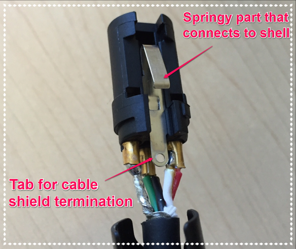
And thinking what to do with that (my box will be made of plastic), i came across this note from Benchmark's @John_Siau :


that links to an additional note by Neutrik.

In any case, what Neutrik and Benchmark tell/do is the following:

Neutrik:
"Typically, chassis connectors need to be grounded. The industry best practice is generally to tie all of the chassis connector shells, pin 1 (cable shields), and the enclosure shield to a common ground."

"Two cases where it becomes necessary to wire the chassis connectorʼs specialized shell contact to a chassis ground are: (a) when using non-conductive (plastic, wood, specially painted, etc.) panels, and/or (b) cases where you want to jumper the shell contact to pin 1."

Benchmark:
"Benchmark bonds pin 1 of XLR chassis connectors directly to chassis ground.Benchmark leaves the cable tab unterminated on all analog XLR cables, but terminates this tab on AES digital XLR cables." (underline is mine)

And now i wonder if my schematic should look like this:
1678003302968.png


and most importantly, if i need to look for an specific xlr cable with the shield connected to the tab, because at least Cordial (the ones i always buy) does not make it clear enough to me in their schematics... i will have to go with a multimeter to the shop...

1678004033443.png

does this mean pin 1 to shield AND to "G" pin. or only to shell?
 

KSTR

Major Contributor
Joined
Sep 6, 2018
Messages
2,819
Likes
6,330
Location
Berlin, Germany
The G(ND) pin -- bad naming, btw -- of those Neutrik NC3FAx2 is a separate contact that allows to connect to the metal front panel and to the metal shell of the inserted plug. There is a small nose protruding the seating plane which is intended to bite into the chassis metal. Same goes for the counterpart NC3MAx. This is to apply the concept of a full Faraday shield, cables being the extension of a metal chassis. The nose-bite-into-chassis contact tends to be unreliable, though, so you should definitely mount your PCB with many many GND contact points to your metal chassis but you do also connect that G pin directly to your GND on the PCB.
As for best possible RF shielding, the pro's choice would be the metal frame chassis connectors (B series, NC3FBH2-E and NC3MBH-E) together with EMC variants of the cable connectors.

The general assumption here is that the cable itself does not connect the cable plug's shell --- which may or may not be the case. The official standard is that cable-side connectors shall leave it open and only chassis-side connectors shall contact it, and the reason is electrical safety, preventing shocks from malfunctioning equipment. This means when extending an XLR cable with another XLR cable, the joint is not shielded as both shells are open and therefore some microphone cables connect the shell on the male side, just like the metal microphone body does.
However, the EMC cable connectors of either gender always do connect the shell to pin1/shield via small capacitor (no safety problem) and RF-isolate the pin 1 with a ferrite bead. When extending XLR cables, you shall not mix with regular types.

XLR connections look easy and straightforward at first glance but there are many subtle details to consider, depending on the planned use case.
 
  • Like
Reactions: MCH
OP
M

MCH

Major Contributor
Joined
Apr 10, 2021
Messages
2,679
Likes
2,301
XLR connections look easy and straightforward at first glance but there are many subtle details to consider, depending on the planned use case.
The more i dig... the more that i agree with you....
IMG_20230305_192851.jpg

(from Amphernol catalog)
 

Edgar

Member
Forum Donor
Joined
Mar 2, 2021
Messages
29
Likes
17
Location
Bangkok
I have a question related to this, and I found this thread when I searched for AES3 termination.
I just received a minDSP SHD-Studio which has XLR outputs with AES3 (or is it AES-EBU?) signals.
I like to look at the output signals with my digital oscilloscope. I am still waiting for my speakers which should arrive in a few days.

I guess I could just connect the oscilloscope like this:
Channel 1 to XLR Pin 2 (data+)
Channel 2 to XLR Pin 3 (data-)
Ground terminal of the oscilloscope to XLR Pin 1 (ground)

Will this show the correct signal? Or do I need a 110 Ohm resistor between the pins 2 and 3, or two 55 Ohm resistors between pin 2 and ground and pin 3 and ground?
Or should I connect a transformer between pins 2 and 3? I have a Pulse PE-65612NL which I could use. Or how to do this?

My idea about the termination with resistors comes from termination of the CAN-BUS, which needs 120 Ohm termination, used in automobiles.

My "project" is for my learning purpose only. In the moment I don't plan to use or convert the AES signal for anything self-made.

Thanks
 
Top Bottom