• WANTED: Happy members who like to discuss audio and other topics related to our interest. Desire to learn and share knowledge of science required. There are many reviews of audio hardware and expert members to help answer your questions. Click here to have your audio equipment measured for free!

catch22

Member
Forum Donor
Joined
Feb 10, 2024
Messages
68
Likes
29
Location
Ireland
Hi all,

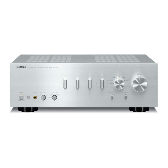
I created a topic for the power-on issue that I have with my Yamaha A-S700.
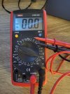
In short, sometimes it would power on, sometimes wouldn't. The problem is rectified sometimes by physically disconnecting and removing the power cord. Gradually becoming more stubborn over time. Yesterday could not switch on at all, today switched on once - i.e. eventually became totally unmanageable until fixed.

Not to flood this thread, the link is here

Experts, can you have a look please?

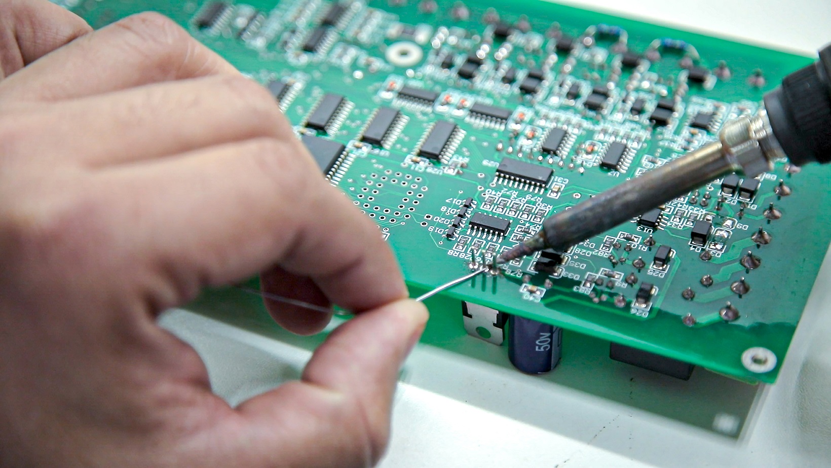
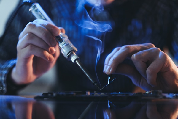
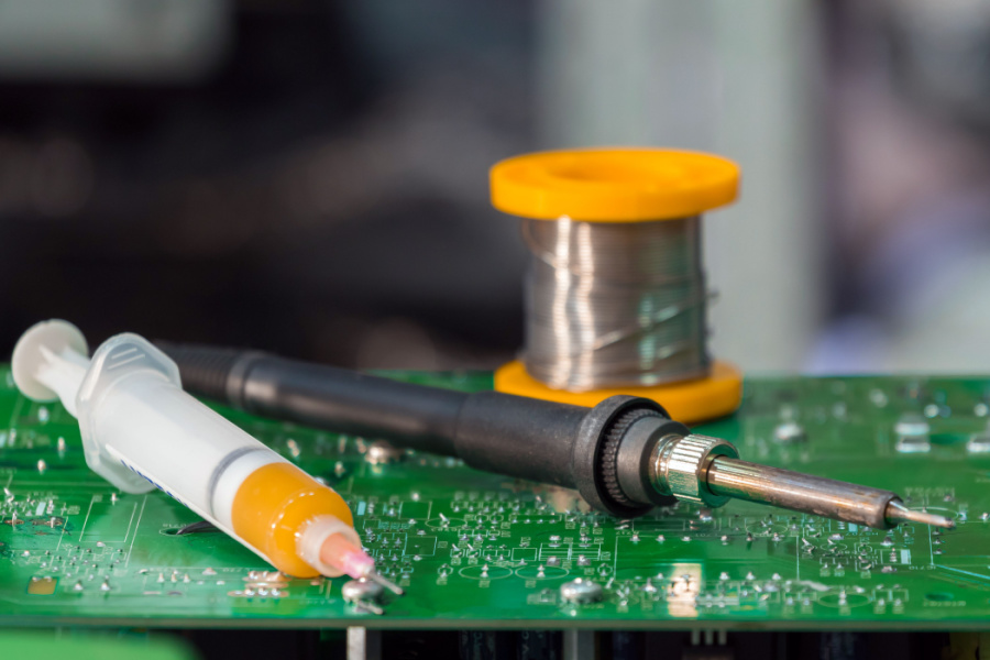
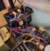
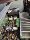
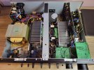
A couple of pictures of inside Yamaha A-S700 to stay on topic :)
 

Attachments

  • 20240310_113712.jpg
    20240310_113712.jpg
    363.1 KB · Views: 47
  • 20240310_113758.jpg
    20240310_113758.jpg
    269.4 KB · Views: 48
  • 20240310_120000.jpg
    20240310_120000.jpg
    388 KB · Views: 44
Last edited:

audiofooled

Addicted to Fun and Learning
Joined
Apr 1, 2021
Messages
533
Likes
594
It won't turn on until power circuit reads that it has stable power. I'm no expert, but it could be anything on the power board in the first picture, loose connection, bad solder joint, failed component, maybe a dodgy power relay... Hopefully someone would have a word of practical advice on what and how to test.
 
OP
TheBatsEar

TheBatsEar

Major Contributor
Forum Donor
Joined
Jun 16, 2020
Messages
3,191
Likes
5,189
Location
Germany
If it where mine, i would start by reflowing all the solder points and measure all the voltages.
 

Doodski

Grand Contributor
Forum Donor
Joined
Dec 9, 2019
Messages
21,639
Likes
21,916
Location
Canada
If it where mine, i would start by reflowing all the solder points and measure all the voltages.
I agree after ~55K repair units completed I can easily testify that the first order for this sort of issue is to reflow solder and clean the PCB after and use a magnifier to inspect the joints all over the PCBs... Take out the PCBs so you don't leave joints that are inaccessible due to being hidden by the chassis metal. Don't even try to trouble shoot this sort of issue before reflowing the solder because amps must be checked and soldered anyway before putting them back into service. :D
 

catch22

Member
Forum Donor
Joined
Feb 10, 2024
Messages
68
Likes
29
Location
Ireland
If it where mine, i would start by reflowing all the solder points and measure all the voltages.

Thanks,

The only thing I measured was this below, because it was requested in the Service Manual.
1) When I manage to successfully power the amp on: my measured voltage between R112 and R136 is 1.1mV immediately after switch on, and slowly creeping up to 3mV within 10 min. (I didn't wait for 60 min though) - which is, according to the Service manual, well within the healthy boundaries.
2) When the unit fails to switch on, the measurement is (not surprising probably) 0.0mV - with power button depressed and power cord attached.
1710112004353.png


Otherwise, I can blindly follow the checklist, where and what to check, but here my knowledge ends :)
To my great regret if I am honest.
 
Last edited:

Doodski

Grand Contributor
Forum Donor
Joined
Dec 9, 2019
Messages
21,639
Likes
21,916
Location
Canada
Thanks,

The only thing I measured was this below, because it was requested in the Service Manual.
1) My measured voltage between R112 and R136 is 1.1mV immediately after switch on, and slowly creeping up to 3mV within 10 min. (I didn't wait for 60 min though) -
which is, according to the Service manual, well within the healthy boundaries. This is when I manage to successfully power the amp on.
2) When the unit fails to switch on, the measurement is, not surprising, 0.0mV - with power button depressed and power cord attached.
View attachment 355500


Otherwise, I can blindly follow the checklist, where and what to check, but here my knowledge ends :)
I think you are associating one thing with another thing and the timing relationship of the similarity with the fault that is present. I don't believe the bias adjust is the issue. Have you checked the offset voltage at the speaker terminals? It should be like maybe 30mV or less. It varies from amp to amp but 30mV or less is average for amps.
 

catch22

Member
Forum Donor
Joined
Feb 10, 2024
Messages
68
Likes
29
Location
Ireland
I think you are associating one thing with another thing and the timing relationship of the similarity with the fault that is present. I don't believe the bias adjust is the issue. Have you checked the offset voltage at the speaker terminals? It should be like maybe 30mV or less. It varies from amp to amp but 30mV or less is average for amps.
I measured that only because the Service Manual asked to do that. Otherwise I have no expertise to analyse the fault unfortunately, thanks for suggesting other measurements.
My point is, when the unit is normally on, there is no abnormality in sound quality or otherwise. I did not notice.
The only issues is that more often than not it would not switch on at all.
In the thread that I created there was a suggestion by @Glint that it may be C254. Do you also think this may be the cause?
 

Doodski

Grand Contributor
Forum Donor
Joined
Dec 9, 2019
Messages
21,639
Likes
21,916
Location
Canada
In the thread that I created there was a suggestion by @Glint that it may be C254. Do you also think this may be the cause
What is C254 and how did one come to this conclusion? Do you have a schematic? The fault could be caused by a multitude of different components or simply by bad solder and a crack in a joint or a thermal issue is possible too hence the delay in the relay after power ON. But this is not rocket science and the fault can and will be solved with analysis, troubleshooting and diagnosis and then confirmation of repair is required to confirm the actual fault has been solved and there are not multiple faults as is common all too often.
 

catch22

Member
Forum Donor
Joined
Feb 10, 2024
Messages
68
Likes
29
Location
Ireland
What is C254 and how did one come to this conclusion? Do you have a schematic? The fault could be caused by a multitude of different components or simply by bad solder and a crack in a joint or a thermal issue is possible too hence the delay in the relay after power ON. But this is not rocket science and the fault can and will be solved with analysis, troubleshooting and diagnosis and then confirmation of repair is required to confirm the actual fault has been solved and there are not multiple faults as is common all too often.
Yes, the schematics of Main is in service manual on page 47

1710113909299.png


Exactly the same behavior as mine was reported for other Yamaha models (with somehow similar shcematic of power module) and several reported successful fix after replacing of similar cap in that design (original thread here https://www.avforums.com/threads/yamaha-dsp-ax861se-intermittent-power-on.2247151/)

But this is not rocket science and the fault can and will be solved with analysis, troubleshooting and diagnosis and then confirmation of repair is required to confirm the actual fault has been solved and there are not multiple faults as is common all too often.
That's exactly why I raised it here... Or you are essencially saying I have no hope without professional help? :) :(
 

Doodski

Grand Contributor
Forum Donor
Joined
Dec 9, 2019
Messages
21,639
Likes
21,916
Location
Canada
Yes, the schematics of Main is in service manual on page 47

View attachment 355502

Exactly the same behavior as mine was reported for other Yamaha models (with somehow similar shcematic of power module) and several reported successful fix after replacing of similar cap in that design (original thread here https://www.avforums.com/threads/yamaha-dsp-ax861se-intermittent-power-on.2247151/)


That's exactly why I raised it here... Or you are essencially saying I have no hope without professional help? :) :(
I am saying that it is not impossible to figure out circuitry and mechanical issues causing faults with effort and possibly some measurements. So don't get worried. Keeping in mind that this is remote tech support so things are not like being there and handling the diagnosis and repair myself or by any capable person here at ASR that decides to help IF the repair can safely be attempted. There are many things occurring as well as some possibly dangerous voltages in certain areas and the possibility of causing additional faults due to not being a expert in repairs of electronics. So we will need to decide if this is to proceed based on safety, ability and sensibility.

I read the link you provided and have decided based on my experience of about 55K repairs completed in my electronics repair work to not go chasing something that is unproven and random. The best approach is to take a fresh new approach and diagnose accordingly. Chasing faults in circles is the #1 enemy of repair work and following a persons' suggestions or old internet details is not sensible. But it was a good find you found there for sure. I see you internet searched the issue.

-Firstly do you know how to solder, have a proper soldering iron and have ~63/37 rosin core solder that is designed and intended for reworking a printed circuit board like the one in this Yamaha amp?
-Are you capable of disassembling the entire unit to inspect all the solder joints @ the PCBs and then resolder all the bad ones and then use a magnifier to inspect them and make sure nothing escaped you, clean the PCB with isopropyl alcohol and then reassemble it the same way it was as new?
-Do you have a decent multimeter to measure milliVolts and up to a 200VDC range and with diode check too?
-Do you have a table or workbench that can accommodate/fit all this gear and repair equipment while you work on the amp?
-Finally how much is this unit worth $$$ to you. I ask because buying tools and chemical and cleaners adds up fast.

Consider this $ expense for repair stuff and you may well be better off with a new unit. If you want to try replacing C254 you can and you will need stuff like I mentioned. :D
What do you think now?
 

Dimitri

Senior Member
Joined
Jan 28, 2018
Messages
368
Likes
427
Location
Valencia California
Anytime there is a "progressively worsening" power ON problem with a unit that uses a stand-by supply voltage the first suspect is the one capacitor responsible for waiting long enough to sense someone pushed the power On button.

I've had the symptom on a Carver receiver (it would either turn on and stay on OR turn on and turn off after a second or less - finally it would just not turn on.) The Carver uses a 220uF capacitor on the standby supply. It measured as 50nF or as I like to call it "absent" !

In this case it's not quite the same but we still have a capacitor "responsible" for powering on.

So yes, it could be a great number of things, but when you are near the Serengeti , the sound of hoofs IS zebras. :)
 
Last edited:

Doodski

Grand Contributor
Forum Donor
Joined
Dec 9, 2019
Messages
21,639
Likes
21,916
Location
Canada
Anytime there is a "progressively worsening" power ON problem with a unit that uses a stand-by supply voltage the first suspect is the one capacitor responsible for waiting long enough to sense someone pushed the power On button.
I agree fully 100%. Additionally to that I have oftentimes seen donut shaped rings of broken solder on hot running transistors that caused some pretty strange thermally delayed Power ON action and protection circuit engagement that was intermittent at both turn ON and the resulting turn OFF... But yeah that cap could be a issue for sure. I suspect everything when dealing with older amps and do the full service routine so I get all the bad stuff out and can provide a good warranty. That includes reworking all the PCBs. It takes about a hour for me to completely disassemble a amp like this one and reassemble and get ready for test. :D
 

catch22

Member
Forum Donor
Joined
Feb 10, 2024
Messages
68
Likes
29
Location
Ireland
I am saying that it is not impossible to figure out circuitry and mechanical issues causing faults with effort and possibly some measurements. So don't get worried. Keeping in mind that this is remote tech support so things are not like being there and handling the diagnosis and repair myself or by any capable person here at ASR that decides to help IF the repair can safely be attempted. There are many things occurring as well as some possibly dangerous voltages in certain areas and the possibility of causing additional faults due to not being a expert in repairs of electronics. So we will need to decide if this is to proceed based on safety, ability and sensibility.

I read the link you provided and have decided based on my experience of about 55K repairs completed in my electronics repair work to not go chasing something that is unproven and random. The best approach is to take a fresh new approach and diagnose accordingly. Chasing faults in circles is the #1 enemy of repair work and following a persons' suggestions or old internet details is not sensible. But it was a good find you found there for sure. I see you internet searched the issue.

-Firstly do you know how to solder, have a proper soldering iron and have ~63/37 rosin core solder that is designed and intended for reworking a printed circuit board like the one in this Yamaha amp?
-Are you capable of disassembling the entire unit to inspect all the solder joints @ the PCBs and then resolder all the bad ones and then use a magnifier to inspect them and make sure nothing escaped you, clean the PCB with isopropyl alcohol and then reassemble it the same way it was as new?
-Do you have a decent multimeter to measure milliVolts and up to a 200VDC range and with diode check too?
-Do you have a table or workbench that can accommodate/fit all this gear and repair equipment while you work on the amp?
-Finally how much is this unit worth $$$ to you. I ask because buying tools and chemical and cleaners adds up fast.

Consider this $ expense for repair stuff and you may well be better off with a new unit. If you want to try replacing C254 you can and you will need stuff like I mentioned. :D
What do you think now?
Thank you very much for your well elaborated answer. Let me answer.
I do have basic soldering skills, a multimeter from mv to 1000VDC/750AC,- a soldering iron, and some solder - although not sure 63/37 if something else. These are layman's tools, not expensive ones. I do understand the safety concerns when working with high voltages.

Money-wise: if look purely from money perspective, the price of the amp around 250 Eur or so. Electronics repair looks like a disappearing profession at least here in Ireland. I found a couple of guys who are rather semi-pro who combine skills and passion. They would fix it, if it is just this same capacitor, like many here guessed, starting from 50, and anything above if it is something else.

But let me try to elaborate more on my motivation behind this attempt.
If it was only a question of money and effort spent on professional repair vs. attempt to repair myself, the professional repair would have easily won.
For me, however (and I am sure for many people on asr) sound/electronics/tinkering is a hobby and not always following cold logic. This is about enjoying spare time and letting yourself doing what you like. Noone is here because we "have" to have these complicated sound setups. It is ok to spend more on the hobby, than we really "need"- if it is satisfying. For example, I do regret that I do not have enough knowledge of electronics. I always wanted but never dig deep enough because the learning curve was too steep.
I guess you and other experts, who spent thousands of hours can look at a schematic diagram and "see "all current flows and instantly understand what the diagram depicts - perhaps in the same way as musicians will glance at music notations and "read" and "hear" it.


I accept will I never have this level, but at the same time it doesn't mean I cannot even start - I do enjoy the learning curve.
For example, yesterday was the first time in my life I heard about "DC offset" - from you, I managed to measure it and I want to know more. Would I have learned about DC offset, had I just brought the amp for professional repair? No :)

[ Spoiler: Something is going on with DC Offset: in the Right channel it is 20mv, the Left is way higher cca 80mv ! ]

Speaking of the capacitor. For you, as a pro, this may come as a surprise: for a layman here in Ireland, sourcing a single component of 0.022uF/630V (cost of few cents to a euro) would be in total 20+ euro. In which 5 euro is 5pcs of the capacitor and another 16 are shipment since they don't have any brick and mortar presence. Amazon has capacitor sets of 100s various nominals for the same 20 euro, but none of them has 0.022uF/630V
 
Last edited:

Doodski

Grand Contributor
Forum Donor
Joined
Dec 9, 2019
Messages
21,639
Likes
21,916
Location
Canada
so, a month project for me :)
I've been handling tools and mechanisms in the form of an assortment of large and small machinery since age 6 or 7 when I received my first complete new Craftsman Mechanics tool box for Christmas. So disassembling and reassembling an amp is pretty simple now. :D
 

Doodski

Grand Contributor
Forum Donor
Joined
Dec 9, 2019
Messages
21,639
Likes
21,916
Location
Canada
Money-wise: if look purely from money perspective, the price of the amp around 250 Eur or so. Electronics repair looks like a disappearing profession at least here in Ireland. I found a couple of guys who are rather semi-pro who combine skills and passion. They would fix it, if it is just this same capacitor, like many here guessed, starting from 50, and anything above if it is something else.
A fee of 50 Euro is reasonable for sure.
I guess you and other experts, who spent thousands of hours can look at a schematic diagram and "see "all current flows and instantly understand what the diagram depicts - perhaps in the same way as musicians will glance at music notations and "read" and "hear" it.
Not always. Some of the stuff is very convoluted and requires major mental somersaults and multiple pages of the schematics open simultaneously. The reality is this is a repair unit and it is not operating properly so to expect everything to be operating as electronic theory denotes is not reality. and additionally as another example... When dealing with mechatronics for example it is pretty much an unwritten rule that there will be electronic faults and mechanical faults simultaneously which makes things very interesting if not impossible for some people that don't have the patience and drive to divide and conquer the repair(s). So no we are not like musicians LoL. Of which I admire greatly.
I accept will I never have this level, but at the same time it doesn't mean I cannot even start - I do enjoy the learning curve.
For example, yesterday was the first time in my life I heard about "DC offset" - from you, I managed to measure it and I want to know more. Would I have learned about DC offset, had I just brought the amp for professional repair? No :)

[ Spoiler: Something is going on with DC Offset: in the Right channel it is 20mv, the Left is way higher cca 80mv ! ]
That DC offset of 80mV needs to be looked into to see what is happening there. A DC offset will cause the woofer to be positioned a bit inward or a bit outward dependent on if the voltage is a positive or a negative voltage at the speaker terminal. That creates issues for the woofers and tweeters etc. It also creates a constant current flow through the amp that is undesirable when the amp is in the quiescent state. As well it is just sloppy calibration IF there is a DC offset trimming potentiometer at the power amplifier circuitry. We'll look into that a bit.
Speaking of the capacitor. For you, as a pro, this may come as a surprise: for a layman here in Ireland, sourcing a single component of 0.022uF/630V (cost of few cents to a euro) would be in total 20+ euro. In which 5 euro is 5pcs of the capacitor and another 16 are shipment since they don't have any brick and mortar presence. Amazon has capacitor sets of 100s various nominals for the same 20 euro, but none of them has 0.022uF/630V
Yes, this is the way nowadays. It sometimes gets worse if a repair shop. The parts suppliers may want a minimum invoice amount in the hundreds of dollars so to place a order the shop must require whatever amount the supplier determines as their minimum invoice amount. This one of many of the reasons why it is difficult to find small repair shops nowadays.

OK so you desire to delve into your Yamaha amplifier at the circuitry level and at the craftsman level of reworking a PCB, diagnosing, troubleshoot, repairing and then the most important part is to confirm the repair and make sure you got the bad stuff out and that everything is operating properly before putting the lid back on and screwing it together.

Do you have a worktable/workbench of a large size where you can leave the amp disassembled over days or weeks as you progress through the servicing/repair of the amp? You are going to need to be comfortable so the table size should be able to easily accommodate the amp in multiple pieces, the paperwork/service literature if you need to spread it out beside the amp and have a soldering iron and all your hand tool laid out in a easily accessible methodology. Part of making electronics repair effective is being organized. Poorly organized service people always have issues and extra work because they cut corners and electronics does not work that way.

Is your solder like 60/40 or something like that and it MUST be rosin core and not acid core. Acid core is for copper plumbing pipes... not delicate PCBs.
Show me your soldering iron. I need to make sure you are good to go for soldering because a good iron can do stuff that a improper sized iron cannot do and a improper sized iron will cause damage to the delicate PCB and that makes for lots of extra work hours that needs to be avoided. The premise of electronic service is being non-invasive, not inducing more issues or faults while servicing it and having impeccable craftsmanship so that after you are finished and clean the PCBs with isopropyl alcohol it is very difficult to determine if somebody has actually been inside the unit working on it.

Additionally as I mentioned before this is a remote operation being done thru you and that means mistakes can happen for so many simple reasons. So keep in mind this servicing of the amp might cause an issue in the amp somewhere along the way. This is purely for your own intrigue and curiosity so this is pretty casual stuff.
Also show me your multimeter and the test leads/wires with the probes. Its critical that it is capable of probing accurately without too much effort and fussing over the use of them. Probes are something very personal LoL. Techs and engineers are known to spend hundreds of dollars on probes because they want very nice ones for all the right reasons.

I think I should have addressed most of your comments but if I missed anything bring it to my attention. :D
 
Last edited:

Doodski

Grand Contributor
Forum Donor
Joined
Dec 9, 2019
Messages
21,639
Likes
21,916
Location
Canada
@catch22 I'm sure you have a digital camera and that will be very handy because you should snap a ton of images from various angles and stuff so you have reference for later use if you get confused etc. Also a new Sharpie felt pen is really nice for marking wiring connectors so that you can fit them all back in the respective positions when you reassemble the amplifier. Nearly all the connectors by design will be different although it does happen that sometimes there are identical sizes and package types and that can make things mind boggling and bit scary when deciding to plug a connector together that you are not sure is the proper mate for it. :D
 

Audiofire

Addicted to Fun and Learning
Joined
Feb 8, 2022
Messages
637
Likes
361
Location
Denmark
Jim Smith says relying solely on the flux in solder wire is unreliable wetting, which I thought is interesting:

Interesting again is that solderability is not determined by a fixed high temperature, but instead wetting (and liquidus temperature):

Interesting for those who need to know flux properties:
 

catch22

Member
Forum Donor
Joined
Feb 10, 2024
Messages
68
Likes
29
Location
Ireland
I've been handling tools and mechanisms in the form of an assortment of large and small machinery since age 6 or 7 when I received my first complete new Craftsman Mechanics tool box for Christmas. So disassembling and reassembling an amp is pretty simple now. :D
I'm good with mechanical work, disassembly and assembly :) It's the electronics knowledge that I lack..

Oh you reminded me of IPA. I must have a can somewhere. I used to use it to clean inside old manual lenses,. that disassembly and assembly is intricate job.. :)
 

catch22

Member
Forum Donor
Joined
Feb 10, 2024
Messages
68
Likes
29
Location
Ireland
I think I should have addressed most of your comments but if I missed anything bring it to my attention. :D
I've got a mentor for the repair :) Appreciated :) Sorry, I just got home it's past midnight, I will respond in details tomorrow. Yep, plenty of space in the shed to lay the components on a table
 

Attachments

  • 20240312_002427.jpg
    20240312_002427.jpg
    244.1 KB · Views: 24
Top Bottom