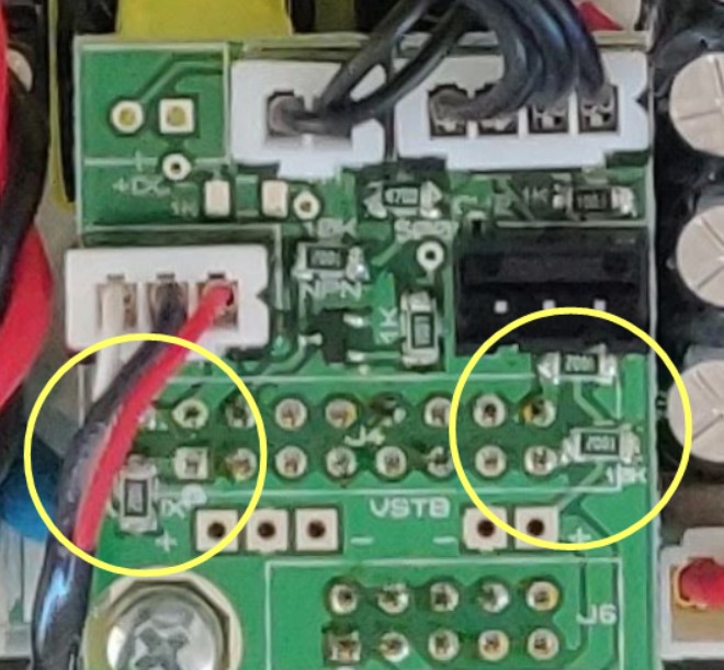
I realize this is going to sound hokey, but on every single thing I own that has an LED that's waaaaaay too bright, I use black Sharpie to color whatever plastic surface/lens the light comes through. It's effective, you can make it not even noticable, and you can trivially remove it with a little alcohol on a cotton swab if you ever want/need to.
Not hokey at all - as I was falling asleep last night I thought, "What if I just used a Sharpie?" I wasn't sure how well it would work, though - specifically how even the blacking-out would look and whether it would be removable later. So I appreciate your report! I'll probably try it.
You probably have seen that on Ghentaudio builds, I'm quite sure there no such a switch on Audiophonics builds
Ah, that must have been it - explains why my searches turned up nothing. Many thanks!
Though I like Audiophonics amps, I don't have the same experience.
The units I have buzz a bit (not in the speakers, I mean the units themselves) when connected to the power outlet (even on sleep mode), and do get warm. I have a MPA-S252NC and a HPA-S500NC. Still I would buy again as those are great products for the price.
I also have this buzz from the unit itself. But it is so quite and it is actually not audible at 30 cm distance. Thus, this is an non-issue for me. I am very happy that I have zero noise floor from my speakers and no pop at on/off.
I don't hear any buzzing on mine. However, I have my unit connected to a DC blocker - I had to get one because my prior amp has a giant toroidal transformer that would quietly but audibly buzz, no doubt from dirty AC on my local municipal grid.
From what I've read, toroidals are more susceptible to buzzing than conventional transformers, and the transformers in the Class D amps aren't terribly large, so it's possible the mechanical buzzing you're hearing could be from something else. But the fact that the sound is not very loud, can't be heard from far away, is not coming through the speakers, and apparently is not experienced by most folks, suggests to me that DC in your AC feed might be the culprit.