
-
Welcome to ASR. There are many reviews of audio hardware and expert members to help answer your questions. Click here to have your audio equipment measured for free!
You are using an out of date browser. It may not display this or other websites correctly.
You should upgrade or use an alternative browser.
You should upgrade or use an alternative browser.
KSTR
Major Contributor
U2.1 is just an inverter on the output of U2.2 drawn in a obscure way. U2.2 is a very simple differential I/V. Normally its non-inverting leg would go to ground, but here it goes to the inverted copy of its own output. This a) makes a balanced output but more importantly, b) it automatically keeps the output voltage of the chip's output pins at a constant voltage, sort of an automatic bias system. This one, however, is not a CM servo loop.The I/V stages for the ES9069 and 9039Q2M (they are identical) are nuts to me. So unlike the one for the 9039PRO shown in above post. Can some explain to me how this IV stage works? Why positive feedback on U2.1? Why apply DAC input to both U2.1 filter netwirk and non-inverting input of U2.2? How is this circuit truly balanced?
The same filter circuit (with input V/I converting resistors) is used some for some voltage-output DAC chips and it is a variation of the "super-balanced" differential receiver circuit (https://sound-au.com/articles/balanced-io.htm#s3)
From my understanding it’s servo the dc between the balanced pins out without a servo? For sure no cm servo loop like the thread before.U2.1 is just an inverter on the output of U2.2 drawn in a obscure way. U2.2 is a very simple differential I/V. Normally its non-inverting leg would go to ground, but here it goes to the inverted copy of its own output. This a) makes a balanced output but more importantly, b) it automatically keeps the output voltage of the chip's output pins at a constant voltage, sort of an automatic bias system. This one, however, is not a CM servo loop.
The same filter circuit (with input V/I converting resistors) is used some for some voltage-output DAC chips and it is a variation of the "super-balanced" differential receiver circuit (https://sound-au.com/articles/balanced-io.htm#s3)
Thank you...though I don't understand the merits of this circuit over the one in the 9039PROU2.1 is just an inverter on the output of U2.2 drawn in a obscure way. U2.2 is a very simple differential I/V. Normally its non-inverting leg would go to ground, but here it goes to the inverted copy of its own output. This a) makes a balanced output but more importantly, b) it automatically keeps the output voltage of the chip's output pins at a constant voltage, sort of an automatic bias system. This one, however, is not a CM servo loop.
The same filter circuit (with input V/I converting resistors) is used some for some voltage-output DAC chips and it is a variation of the "super-balanced" differential receiver circuit (https://sound-au.com/articles/balanced-io.htm#s3)
 .
.Now, as far as the wide bandwidth (ok, 2.6KHz) CM servo I alluded to earlier for the 9039PRO:
a) What are some of the common mode sources of noise to the amp inputs, apart from the 50/60Hz mains and their harmonics, that would justify a wideband CM circuit?
b) If the 51pF filter cap was removed, would a full-range CM filter make sense? What are any plusses and minuses?
Thanks!
One op amp less. I'm not sure abut the penalties....Thank you...though I don't understand the merits of this circuit over the one in the 9039PRO
Now, as far as the wide bandwidth (ok, 2.6KHz) CM servo I alluded to earlier for the 9039PRO:
a) What are some of the common mode sources of noise to the amp inputs, apart from the 50/60Hz mains and their harmonics, that would justify a wideband CM circuit?
b) If the 51pF filter cap was removed, would a full-range CM filter make sense? What are any plusses and minuses?
Thanks!
a) noise conducted from the digital side of the DAC, glitches...
b) oscillations, 51pf please consider the gain BW product
KSTR
Major Contributor
The circuit, when seen as a black box, does the same thing as the 9039pro circuit. It's a fully differential operational amplifier set up as a differential filter (see Fig.26).Thank you...though I don't understand the merits of this circuit over the one in the 9039PRO
Now, as far as the wide bandwidth (ok, 2.6KHz) CM servo I alluded to earlier for the 9039PRO:
a) What are some of the common mode sources of noise to the amp inputs, apart from the 50/60Hz mains and their harmonics, that would justify a wideband CM circuit?
b) If the 51pF filter cap was removed, would a full-range CM filter make sense? What are any plusses and minuses?
Thanks!
The 9039q2m circuit, the super-balanced differential I/V (differential low-pass filter), is the simplest configuration for this besides specialized fully differential amplifier chips and it does work well / is pretty robust.
ESS "current output" DAC have higher even-order distortion and noise when looking at the individual outputs. Proper summing of the outputs removes most of the even-order distortion because because of symmetry. Therefore, removing the CM content is absolutely required for best performance. And yes, balanced internal signal paths in a DAC is always good for low interference.
In the 9039pro circuit, the CM loop amp needs to have some local compensation because the main amps are the slave amplifiers in the composite loop and would add excessive phase if the master operated "wide open" wrt bandwidth, causing instability/oscillations.
For a similar reason, BTW, we find this 33pF cap in the feedback of the inverter in the 9039q2m circuit.
CleanSound
Major Contributor
- Joined
- Apr 30, 2023
- Messages
- 1,654
- Likes
- 2,609
Could this be it?

OP
- Thread Starter
- #69


Bleib
Major Contributor
- Joined
- May 13, 2021
- Messages
- 2,445
- Likes
- 4,520
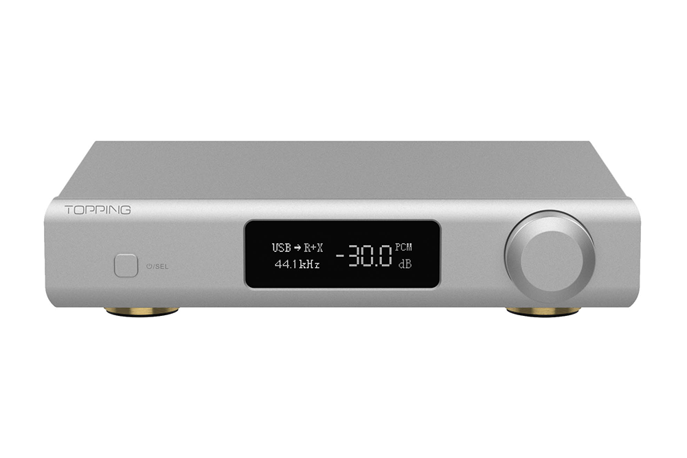
TOPPING D90 III SABRE Dual ES9039SPRO Digital to Analog Convertor (DAC
shenzhenaudio.com: professional headphone, earphone, amplifier, dac, decoder, hifi player, cable supermarket. you will find good price here.
I was hoping for a UI update similar to the new D70’s.TOPPING D90 III SABRE Dual ES9039SPRO Digital to Analog Convertor (DAC
shenzhenaudio.com: professional headphone, earphone, amplifier, dac, decoder, hifi player, cable supermarket. you will find good price here.shenzhenaudio.com
Bleib
Major Contributor
- Joined
- May 13, 2021
- Messages
- 2,445
- Likes
- 4,520
Yes, the optional VU-meter for instance is quite nice. In fact, the D70pro display looks a lot nicer.I was hoping for a UI update similar to the new D70’s.
According to some other posts PEQ support will be added to D90 III later on at least.
Similar threads
- Locked
- Replies
- 30
- Views
- 2K
- Replies
- 5
- Views
- 2K
- Replies
- 13
- Views
- 4K