• WANTED: Happy members who like to discuss audio and other topics related to our interest. Desire to learn and share knowledge of science required. There are many reviews of audio hardware and expert members to help answer your questions. Click here to have your audio equipment measured for free!

Does Phase Distortion/Shift Matter in Audio? (no*)

Can you expand on what you specifically mean here? Time alignment between the drivers needs to be repeated? Can you describe exactly what filters you are applying?

LR4 HPF @ 50Hz, and LR4 LPF @ 50Hz.

1717000667563.png


With reference to the above diagram, red is the LPF, green is the HPF, and brown is the sum of LPF + HPF. I have placed a marker at 50Hz.

At 50Hz, the phase of the LPF is -179 deg. The HPF is -158 deg. I have to align both to the tweeter, which itself is rotating phase. To avoid confusing matters, let's say it is at 0 degrees.

Phase = time. We can calculate the time discrepancy from the phase angle with t = theta / (360*f). So the LPF is 179/(360*50) = 9.94ms, and the HPF is 8.78ms.

In reality the drivers themselves introduce additional phase rotation, and as mentioned the tweeter probably isn't at 0 degrees. This is why the time alignment procedure needs to be repeated. Regardless, I always repeat the time alignment procedure whenever I make a change to the XO if there are phase changes (there are always phase changes). It's just good practice.
 
LR4 HPF @ 50Hz, and LR4 LPF @ 50Hz.

View attachment 371834

With reference to the above diagram, red is the LPF, green is the HPF, and brown is the sum of LPF + HPF. I have placed a marker at 50Hz.

At 50Hz, the phase of the LPF is -179 deg. The HPF is -158 deg. I have to align both to the tweeter, which itself is rotating phase. To avoid confusing matters, let's say it is at 0 degrees.

Phase = time. We can calculate the time discrepancy from the phase angle with t = theta / (360*f). So the LPF is 179/(360*50) = 9.94ms, and the HPF is 8.78ms.

In reality the drivers themselves introduce additional phase rotation, and as mentioned the tweeter probably isn't at 0 degrees. This is why the time alignment procedure needs to be repeated. Regardless, I always repeat the time alignment procedure whenever I make a change to the XO if there are phase changes (there are always phase changes). It's just good practice.

For a LR4, the LPF and HPF phase response should be identical. If they are not, something is wrong. A LR4 should have 180 deg phase at the crossover frequency, so your LPF is probably correct but there is something wrong with your HPF. It is also possible that you have timing issues in your measurement which are corrupting your results. How are you implementing a timing reference?

The time alignment between sub and woofer should be identical regardless of whether you are using linear phase or minimum phase filters. If they are not, there is something wrong with your approach.

Here is what the individual LPF and HPF responses should look like for a LR4 @ 50 Hz. Note, the high frequency noise in the LPF phase trace is a result of the significant attenuation that has occurred at those frequencies.

LR4 at 50 Hz - Linear Phase vs Minimum Phase - LPF and HPF Magnitude Response.png


LR4 at 50 Hz - Linear Phase vs Minimum Phase - LPF and HPF Phase Response.png


Michael
 
With reference to the above diagram, red is the LPF, green is the HPF, and brown is the sum of LPF + HPF. I have placed a marker at 50Hz.

At 50Hz, the phase of the LPF is -179 deg. The HPF is -158 deg. I have to align both to the tweeter, which itself is rotating phase. To avoid confusing matters, let's say it is at 0 degrees.

Phase = time. We can calculate the time discrepancy from the phase angle with t = theta / (360*f). So the LPF is 179/(360*50) = 9.94ms, and the HPF is 8.78ms.
Hi, I don't know why there should be any phase trace separation between the HPF and LPF.
Electrically there isn't,.....the phase traces lie directly on top of each other.

Something appears amiss with your traces, (if I understand them correctly.)
Are they FFT measurements of the filters? If so, any auto delay finding, loopback timing, etc, ...needs to be ignored. Because it's not real delay/time.

Also, fwiw...the idea that Phase = time is one I've had to purge from my mind. Phase being frequency dependent, and time not being so...simply can't exchange for one another.
Took me forever to fully grasp that...sigh...

haha ...I see Michael just beat me to it :)
 
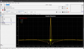
I disagree that the time alignment should be identical with linphase vs. minphase. Here, I have created two LR4's with a corner frequency of 50Hz, linphase and minphase versions.

1717041711490.png


Examination of the impulse display shows that the linphase version (blue/brown) is aligned in the middle of the filter length. Because I have 65536 taps, both LPF and HPF are aligned at position no. 32768.

1717041620883.png


Examination of the LPF and HPF shows that they are aligned at the middle of the impulse peaks. The LPF is lower in amplitude, in brown.

1717041784537.png


Examination of the minphase version on the other hand, shows that they are aligned at the start of the impulse. Again, the LPF is lower in amplitude, in red.

1717041878192.png


The HPF needs to be rotated 404 samples (8.42ms) so that the middle of the impulse peaks align.

Phase is frequency dependent, yes. But you can see that the formula I gave gives you the time delay at that particular frequency, t = theta / (360 * f). It's just a different way of looking at things.
 
That's a real world (cheap) analog LR4 looks like:

(all four channels)

1717060038515.png

(link)
 
why do you think you need to align them at the centre of the impulse? and have you looked at what you just did to how those two filters sum?
Exactly. Aligning the peaks of the impulse response for IIR crossovers is an error. Below is an excerpt from a video by Charlie Hughes of JBL Pro that shows what happens when people make this error.

 
Exactly. Aligning the peaks of the impulse response for IIR crossovers is an error. Below is an excerpt from a video by Charlie Hughes of JBL Pro that shows what happens when people make this error.


An article by Bob Mccarthy (Meyer Sound) on the matter:

 
@Keith_W thank you for sharing your learning process. I am sure it will be very helpful to others.

I think it illustrates a point that I've seen @gnarly repeatedly make, in many ways linear phase crossovers are a lot easier to deal with. Not only is it easier to see impulse alignment, but it is easier to see phase alignment as you know everything should be flat.

Another thing I think this discussion illustrates is that time alignment between drivers should make physical / acoustic sense. If you come up with a relative delay that is not roughly equal to the acoustic offset of the drivers, something is wrong.

Michael
 
Exactly. Aligning the peaks of the impulse response for IIR crossovers is an error. Below is an excerpt from a video by Charlie Hughes of JBL Pro that shows what happens when people make this error.

Lots of interesting and hard to wrap your head around information in this thread.

Regarding the subwoofer time alignment issue I always use the same sweep, limited in FR to 2 octaves above and below the crossover point for the Sub and the mains and then align to the peaks. My understanding when watching this video is that this is correct, is that right? What I don't quite follow is why anyone would use a different sweep for the Mains and Subs in the first place. I am sure I am missing something obvious.

Another question I have is how people go about creating an "acoustic" crossover let's say an LR 4 and how acoustic and electrical filters interact with phase. I read about "flattening" the drivers (which would mean boosting the frequencies above and below the crossover point to allow for the driver roll off) and then applying an LR 4 filter. To me it seems like a lot of filters fighting each other. Why not just take the measured driver response and try to "fit" it to the "electrical" LR4 curves using different filters? When I have done this I notice for an LR 4 I usually end up with 3rd order butterworth HP and LP filter with the 3 dB down point shifted slightly away from target crossover frequency but it of course depends on the drivers, baffle, etc. This "seems" to work and supposedly if the measured FR of the filters match the LR4 target curves it should get you pretty close to what you want. What I get confused about is when I read that a LR 4 uses 2 "cascaded" 2nd order Butterworth Filters (what is the difference between 1 4th order filter and 2 cascaded 2nd order filters?) and I am using a 3rd order Butterworth plus the driver roll off to get a 4 th order filter but not cascading anything. Is this an "error"? Any help wrapping my head around these concepts would be appreciated.
 
Another question I have is how people go about creating an "acoustic" crossover let's say an LR 4 and how acoustic and electrical filters interact with phase. I read about "flattening" the drivers (which would mean boosting the frequencies above and below the crossover point to allow for the driver roll off) and then applying an LR 4 filter. To me it seems like a lot of filters fighting each other. Why not just take the measured driver response and try to "fit" it to the "electrical" LR4 curves using different filters?

Both approaches should have the same result.

I like flattening the driver magnitude / phase response with minimum phase IIR filters as I think it is an easier target to achieve. And once you have flattened the driver's magnitude / phase response it is trivial to try different crossovers, just apply an electrical crossover and it will match your desired acoustic response.

You can certainly take the driver response as-is and use filters to achieve your desired acoustic LR4 response. But those corrections will only be valid for LR4 response and if you want to try a different acoustic crossover you need to develop new filters to achieve your desired acoustic response.

When I have done this I notice for an LR 4 I usually end up with 3rd order butterworth HP and LP filter with the 3 dB down point shifted slightly away from target crossover frequency but it of course depends on the drivers, baffle, etc. This "seems" to work and supposedly if the measured FR of the filters match the LR4 target curves it should get you pretty close to what you want. What I get confused about is when I read that a LR 4 uses 2 "cascaded" 2nd order Butterworth Filters (what is the difference between 1 4th order filter and 2 cascaded 2nd order filters?) and I am using a 3rd order Butterworth plus the driver roll off to get a 4 th order filter but not cascading anything. Is this an "error"? Any help wrapping my head around these concepts would be appreciated.

It will depend on your driver / crossover but when pairing a sealed woofer to a subwoofer, it is common to apply a 2nd order electrical high pass to the woofer to achieve a 4th order acoustic high pass response. And then assuming the subwoofer is relatively flat at higher frequencies, you would apply a 4th electrical low pass to the subwoofer to achieve a 4th order acoustic low pass response.

Pretty much all IIR filters are in practice are achieved by cascading biquads (2nd order filters). If you see an option in a DSP program for a 4th order filter it is likely implementing two cascaded 2nd order biquads to achieve this.

At the end of the day all that matters is the acoustic response and it doesn't really matter how you get there.

Michael
 
Another question I have is how people go about creating an "acoustic" crossover let's say an LR 4 and how acoustic and electrical filters interact with phase.
I wrote an informal paper detailing a mathematical approach to exactly that. I first mentioned it here. PM if interested in a copy.

Edit: Section 6 of the paper addresses this.
 
Last edited:
@Keith_W thank you for sharing your learning process. I am sure it will be very helpful to others.

I think it illustrates a point that I've seen @gnarly repeatedly make, in many ways linear phase crossovers are a lot easier to deal with. Not only is it easier to see impulse alignment, but it is easier to see phase alignment as you know everything should be flat.

Another thing I think this discussion illustrates is that time alignment between drivers should make physical / acoustic sense. If you come up with a relative delay that is not roughly equal to the acoustic offset of the drivers, something is wrong.

Michael

Kind words, thx. :)
and very much agree with the shared learning process.
.
Oh man, how many times have folks straightened me out over on DIY
(where I'm mark100...wish I only had one name for all forums now)
 
Regarding the subwoofer time alignment issue I always use the same sweep, limited in FR to 2 octaves above and below the crossover point for the Sub and the mains and then align to the peaks. My understanding when watching this video is that this is correct, is that right? What I don't quite follow is why anyone would use a different sweep for the Mains and Subs in the first place. I am sure I am missing something obvious.

So I take it you are addressing the problem of uneven HF response Charlie H discusses, by using a sweep 3-4octaves wide around centered around proposed xover freq.?
Pretty clever I think...can't say I've seen others use that technique. Closest I've seen, is the wavelet at xover technique, which an increasing number in pro-audio are stating to tout. I'm gonna try your method.
As far as those using full sweeps, I think those that know what they are doing use 1/3 oct zero phase filtering at crossover, and align the peaks. That fits into between your technique (if i understand it correctly) and wavelets I think.
At any rate, I'd expect all of them properly executed should give close results.

I ditto @mdsimon2 with regard to either way works, pre-flattening response then crossing, or fitting to curved acoustical xover targets.
For me it's simply much easier to EQ to flat, then apply xover. Plus, there's the advantage of easily trying different xover freqs, if already flattened (as Michael mentioned)
Truth be told however, I don't do either. The FIR generators I use, either FirD or Crosslite+, both allow specifying an acoustic target curve, then automatically fitting EQs and xovers to make measurement match the target. It's so dang easy.
 
OK. I have been making linphase FIR's exclusively for years. This is my first time venturing into minphase IIR's. I guess I have a whole bunch of new things to learn.

Do you have opinions pre-ringing and making the FIR taps non symetric?
 
Do you have opinions pre-ringing and making the FIR taps non symetric?

The former yes, the latter no. I haven't tried making asymmetric FIR taps so I don't have an opinion on it. If you have an opinion, I would love to hear yours :)

I have certainly made filters with a lot of pre-ringing, but most of the time the pre-ringing is microscopic and you really need to zoom in to see it. Here is an example.

1717133568563.png


1717133644981.png
 
The former yes, the latter no. I haven't tried making asymmetric FIR taps so I don't have an opinion on it. If you have an opinion, I would love to hear yours :)

You could just take the filters and chop of the leading part…
I don;t have enough real experience to comment, but it would be less ringy.
Some fellow I spoke with, in Sydney I think, suggested that.

I have certainly made filters with a lot of pre-ringing, but most of the time the pre-ringing is microscopic and you really need to zoom in to see it. Here is an example.

^Thanks Bruss^.
 
You could just take the filters and chop of the leading part…
I don;t have enough real experience to comment, but it would be less ringy.
Some fellow I spoke with, in Sydney I think, suggested that.
That most certainly does not do what you want. What's more, the "ringing" may or may not be a problem.

What you want to do if you want to make your constant delay filter into a minimum delay filter is to use a cepstrum to convert the filter to its minimum phase version.


I also award you two ears and the tail for learning how to do that properly.
 
Continuing my reading about phase. I read David Griesinger's paper on proximity available here: http://www.ica2016.org.ar/ica2016proceedings/ica2016/ICA2016-0379.pdf

Summary of what he said: "proximity" is the sensation of being closer or further to a sound source. For example, if you listen to a string quartet and start walking further away, the sound changes from being able to distinguish individual musicians and being able to hear who played which note, to an indistinct fuzzy ball of sound. He says that phase alignment is what creates proximity, and loss of phase alignment causes loss of proximity. This loss of phase alignment is caused by reflections - the further you walk away, the worse it gets.

In home audio, I wonder if the equivalent would be: the minimum phase response of the speaker getting muddied up by the excess phase reflections of the room.

This also leads me to wonder whether loudspeakers that distort the phase response (i.e. any loudspeaker with a minimum phase crossover) would also reduce the "proximity" effect, and whether we should all be aiming for linear phase behaviour from loudspeakers. Opinions?
 
Back
Top Bottom