I would not expect the impedance of the cable itself to change appreciably enough to matter, unless it's simply too small and it encounters Ohmic heating.
If you wish to measure the electrical transfer function as a whole, you would need to measure at the individual speaker terminals.
It also depends on how "good" of a measurement one wishes. At every dissimilar metal joint/connection, there will be a very small offset voltage created by the thermoelectric effect. However, it would be so minor I am incredulous that it'll have any audible effect. Hmm. Possibly for tonearms/cartridges but don't know much about them.
I would assume at audio frequencies, any meaningful variation due to movement would be either lose or cracked conductivity in the circuit with a sub-population of specific situations where a cable is being moved closer or father away from an EMI noise source.
At extremely low amplitudes, RF frequencies, and other non-relevent areas, the triboelectric effect can be the dominate measurement uncertainty factor. That is why typically such measurements are done with fixtures.
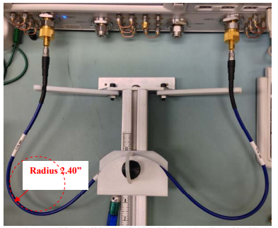
Here is a simple device to measure how large the effect is for a particular cable:
Credit to:
https://www.minicircuits.com/appdoc/AN46-003.html