One of my next projects is a valve amplifier. I built many solid state amplifiers and I'm very happy with these. I always considered valve amplifiers as being vastly inferior to solid state one but nevertheless I would like to build one to measure it and to listen to it. From all the available schematics and projects I saw, the one made by Bob Cordell (C7 KT88) stuck with me and I'm planning to build it. The only notable difference from the schematic published by BC is that I plan to use an ultra linear output transformer. I have a question regarding output transformers in general. Is there a reason to avoid using troridal ones? There is a company (Toroidy) that builds very good transformers in general. I bought several custom transformers from them for the power supply of solid state amplifiers and I can say these are high quality products. As I do not have that much experience with tube amplifiers (I'm still in the process of reading Morgan Jones's book) I do not know if toroidal transformers have any downsides when used as output transformers in tube amplifiers. I can still buy the "classical" Hammond transformers as these have very good reviews allover the internet. Any help is highly appreciated.

-
WANTED: Happy members who like to discuss audio and other topics related to our interest. Desire to learn and share knowledge of science required. There are many reviews of audio hardware and expert members to help answer your questions. Click here to have your audio equipment measured for free!
You are using an out of date browser. It may not display this or other websites correctly.
You should upgrade or use an alternative browser.
You should upgrade or use an alternative browser.
Building a valve amplifier
- Thread starter horias2000
- Start date
OP
- Thread Starter
- #2
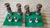
I ordered the PCBs in China and I already got to solder the components on them. The transformers should arrive later this week or early next one. In the end I went with the toroidal transformers from Toroidy. Next I will power everything up and I will adjust all the bias voltages/currents and I will start testing/measuring the prototype. I will post all the adventures here and all the measurements as well. I started a thread on the DIY AUDIO forum as well.
You did Step 1: Morgan Jones. Both "Building Valve Amplifiers" and "Valve Amplifiers" are essential reads. There's a nice blurb on the back from someone very familiar...
Re toroids, their issue is the sensitivity to any idle current offsets. If there's a solid autobias circuit to keep the halves in near-perfect balance, toroids can work very, very well (I say "can" because I don't know that particular company). If you have a few milliamps of unbalance, they will not work well at all. The Hammonds are reasonably OK; if you can find James, they are some of the best out there. I have heard good things about Heyboer, but no personal experience.
If you're ignoring the UL taps, they're of no consequence one way or the other. If you're thinking about configuring the circuit as ultralinear, I strongly recommend you look at Morgan's articles in AudioXpress a couple months back showing why certain tubes work better for it than others.
OP
- Thread Starter
- #4
Thanks for the comments. Yes I read the "Building Valve Amplifiers" book by Morgan Jones (actually I did not get to finish it). I do know the saturation problem of toroidal transformers and I will try to tackle it. In the first iteration I will not use an autobias board but I plan to buy one and use it in the end product.You did Step 1: Morgan Jones. Both "Building Valve Amplifiers" and "Valve Amplifiers" are essential reads. There's a nice blurb on the back from someone very familiar...
Re toroids, their issue is the sensitivity to any idle current offsets. If there's a solid autobias circuit to keep the halves in near-perfect balance, toroids can work very, very well (I say "can" because I don't know that particular company). If you have a few milliamps of unbalance, they will not work well at all. The Hammonds are reasonably OK; if you can find James, they are some of the best out there. I have heard good things about Heyboer, but no personal experience.
If you're ignoring the UL taps, they're of no consequence one way or the other. If you're thinking about configuring the circuit as ultralinear, I strongly recommend you look at Morgan's articles in AudioXpress a couple months back showing why certain tubes work better for it than others.
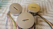
The transformers are built by a Polish company (Toroidy) and they have excellent reputation. I used them in the past for custom toroidal transformers for power amplifiers and I can say they are of very good quality. I read some threads on the DIY Audio forum and all spoke very highly about these transformers. People that used these were very happy with THD and frequency response from these transformers.
The amplifier is based on the KT88 amplifier designed and built by Bob Cordell (PDF is available for free online). I plan to use both UL and fixed bias triode mode and I want to be able to switch between the two modes via a switch.
Here's the problem: the best operating points and load for UL and triode will almost certainly be different. So at least one mode will be running non-optimally. Pick one, optimize for it, then be happy. And absolutely read Morgan's UL articles which may clarify a lot of points for you.The amplifier is based on the KT88 amplifier designed and built by Bob Cordell (PDF is available for free online). I plan to use both UL and fixed bias triode mode and I want to be able to switch between the two modes via a switch.
OP
- Thread Starter
- #6
Yes, definitely the operating points and the compensations for a different transformer will be different from the ones in the article. Will definitely read the articles you mentioned. Thanks for the input.Here's the problem: the best operating points and load for UL and triode will almost certainly be different. So at least one mode will be running non-optimally. Pick one, optimize for it, then be happy. And absolutely read Morgan's UL articles which may clarify a lot of points for you.
OP
- Thread Starter
- #8
In order to calculate the loadline I use the online calculator found here: https://www.vtadiy.com/loadline-calculators/power-stage-calculator/ and I also used the classic pen and paper method by using the JJ KT88 datasheet.
Attachments
OP
- Thread Starter
- #9
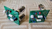
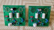
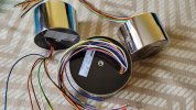
Short update. I just received the transformers from Toroidy and I finalized the PCBA's. This week I will start the testing and measurements. First I will power up the power supply and measure it and then I will power-up the amplifiers and adjust all bias currents and then I will perform some measurements. I'll keep this thread updated once I have more info. I attached some pictures of the PCBAs and of the transformers. I did not have the time to clean the KT88 tube socket solder joints ") Sorry for that
Sorry for that
Sorry for that Attachments
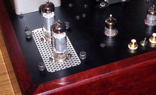
Something that immediately jumps out at me is thermal management. Are you planning to have a slow fan move the air around the output tubes? Otherwise, you may have premature death of either the tubes, the PCB, or both.
OP
- Thread Starter
- #11
I do not plan to have a fan. My estimation was that I will not have any thermal issues considering that I will run the output tubes below half of their rated output power. The estimated output power is around 20-25W. Do you think that the temperature of the output tubes will be an issue?Something that immediately jumps out at me is thermal management. Are you planning to have a slow fan move the air around the output tubes? Otherwise, you may have premature death of either the tubes, the PCB, or both.
Yes. And there may be premature PCB burning. Reliable tube designs will have some means of air flow past the output tubes, whether forced or convective.I do not plan to have a fan. My estimation was that I will not have any thermal issues considering that I will run the output tubes below half of their rated output power. The estimated output power is around 20-25W. Do you think that the temperature of the output tubes will be an issue?
As an example, here's what I did for my amp.
OP
- Thread Starter
- #13
OK, thanks for the heads-up. I will consider some kind of cooling solution. The strange thing is that there is no information regarding temperatures in the datasheet. I would expect something like temperature vs lifetime graph or information like we have for electrolytic capacitors.
Again, it’s not just the tubes (though I’d definitely worry about those as well), it’s also the pcb. I’ve spent a lot of time rebuilding amps where the pcb was burned to the point of cracking and traces peeling and breaking. Better pcb designs will have numerous holes or slits around the output tube bases for convection cooling.OK, thanks for the heads-up. I will consider some kind of cooling solution. The strange thing is that there is no information regarding temperatures in the datasheet. I would expect something like temperature vs lifetime graph or information like we have for electrolytic capacitors.
Lots of good suggestions and information on this can be found in Morgan Jones’s excellent book “Building Valve Amplifiers.”
OP
- Thread Starter
- #15
A quick and short update. I managed to start testing the power supply and the power amplifier. The power supply works just fine as it is. I have the following values:
VHT= 385Vdc (no load), 360Vdc (loaded)
Vdriver= 330Vdc (no load)
Vinput= 188Vdc (no load)
Voutout_screens= 188Vdc
Then I have the lower voltages that are used for gate bias:
Voutput_bias= -20.03Vdc
Vinput_bias= -37.8Vdc
Vdriver_bias= -10.37Vdc
I then proceeded to power the power amplifier and I stared by applying the 385Vdc to the center tap of the output transformer and I adjusted the -20Vdc grid bias to get around 45mA through the output tubes. I will crank up the bias current through the output devices once everything is thoroughly tested. The rest of the amplifier (input stage and driver stage) were not powered at this stage.
I proceeded to power the input stage and the driver stage as well. Unfortunately I was running out of available time and I only got the quickly measure the bias current through the input stage (~2mA - 1mA through each half of the tube) and through the driver stage (~12mA - 6mA through each half of the tube). While powering up the complete amplifier I added an 8OHM resistor on the output winding and I ran the feedback wire back to to the input stage. I did notice some oscillation (of course there is oscillation ) after the output stage tubes warmed up. I did not have the time to dig a bit deeper into this but I did notice that the current through the output tubes went out of balance. One had around 45mA through it and the other one had around 60mA. Nothing alarming but definitely needs looking into.
Next I will power the output stage by itself and I will set the bias and the balance again. After I will power the input stage and the driver stage with the output stage disconnected (either not powered or by disconnecting the coupling capacitors). By doing this I want to precisely set the DC bias balance through the two stages and only after this is set I will connect all three stages together.
The oscillation will most probably still be there and I will start investigating with the scope. I also realized that I forgot to add the R-C zobel network that should be on the 8OHM output (feedback trace). I will add that as well.
The tests above were all done with the output configured a pentode. I will also test with UL to see how it behaves.
The first suspect for the oscillation is the output transformer. Therefore I will add a 1nF+1K between the anode and the screens of the output devices (UL tap and the anode tap of the output transformer) and see what this dose to he oscillation.
Any suggestions are welcome
VHT= 385Vdc (no load), 360Vdc (loaded)
Vdriver= 330Vdc (no load)
Vinput= 188Vdc (no load)
Voutout_screens= 188Vdc
Then I have the lower voltages that are used for gate bias:
Voutput_bias= -20.03Vdc
Vinput_bias= -37.8Vdc
Vdriver_bias= -10.37Vdc
I then proceeded to power the power amplifier and I stared by applying the 385Vdc to the center tap of the output transformer and I adjusted the -20Vdc grid bias to get around 45mA through the output tubes. I will crank up the bias current through the output devices once everything is thoroughly tested. The rest of the amplifier (input stage and driver stage) were not powered at this stage.
I proceeded to power the input stage and the driver stage as well. Unfortunately I was running out of available time and I only got the quickly measure the bias current through the input stage (~2mA - 1mA through each half of the tube) and through the driver stage (~12mA - 6mA through each half of the tube). While powering up the complete amplifier I added an 8OHM resistor on the output winding and I ran the feedback wire back to to the input stage. I did notice some oscillation (of course there is oscillation
) after the output stage tubes warmed up. I did not have the time to dig a bit deeper into this but I did notice that the current through the output tubes went out of balance. One had around 45mA through it and the other one had around 60mA. Nothing alarming but definitely needs looking into. Next I will power the output stage by itself and I will set the bias and the balance again. After I will power the input stage and the driver stage with the output stage disconnected (either not powered or by disconnecting the coupling capacitors). By doing this I want to precisely set the DC bias balance through the two stages and only after this is set I will connect all three stages together.
The oscillation will most probably still be there and I will start investigating with the scope. I also realized that I forgot to add the R-C zobel network that should be on the 8OHM output (feedback trace). I will add that as well.
The tests above were all done with the output configured a pentode. I will also test with UL to see how it behaves.
The first suspect for the oscillation is the output transformer. Therefore I will add a 1nF+1K between the anode and the screens of the output devices (UL tap and the anode tap of the output transformer) and see what this dose to he oscillation.
Any suggestions are welcome
With that current imbalance, you’ve likely saturating the output transformer which isn’t helping.
First thing I’d do for stability is to work on the compensation to shape the open loop gain. If that doesn’t get you there, it’s time to adjust the feedback network lead compensation.
On the net somewhere, there’s a terrific and relevant article by Norman Crowhurst from the 1950s with a title something like Amplifier Adjustments When Fitting A New Output Transformer.
F
freemansteve
Guest
Are there Class-D valve designs out there ?
I know many valves work at RF for radio, but can they be used on the power side of a chopper?
I know many valves work at RF for radio, but can they be used on the power side of a chopper?
DHT 845
Addicted to Fun and Learning
- Joined
- Feb 28, 2021
- Messages
- 509
- Likes
- 444
I only know the opinions from the person who built tube amps, he said that toroidal transformers should be avoided since they spread distortion.One of my next projects is a valve amplifier. I built many solid state amplifiers and I'm very happy with these. I always considered valve amplifiers as being vastly inferior to solid state one but nevertheless I would like to build one to measure it and to listen to it. From all the available schematics and projects I saw, the one made by Bob Cordell (C7 KT88) stuck with me and I'm planning to build it. The only notable difference from the schematic published by BC is that I plan to use an ultra linear output transformer. I have a question regarding output transformers in general. Is there a reason to avoid using troridal ones? There is a company (Toroidy) that builds very good transformers in general. I bought several custom transformers from them for the power supply of solid state amplifiers and I can say these are high quality products. As I do not have that much experience with tube amplifiers (I'm still in the process of reading Morgan Jones's book) I do not know if toroidal transformers have any downsides when used as output transformers in tube amplifiers. I can still buy the "classical" Hammond transformers as these have very good reviews allover the internet. Any help is highly appreciated.
He also was making his own transformers very carefully, with some special cores and winding technics. But as I said, that is and opinion. I believe that many factors matter in tube amps. In power supply capacitors are probably even more important, their total capacity, ESR, by-pass caps etc.
So if you want to build good tube amp for listening make no compromises in the power supply. Good quality oversided transformer is important. As far as polish toroids they are probably good in price/performance ratio but the best sounding tube amps I heard did not used toroids, as far as KT-88 concerned the best I heard is Air Tight ATM-2. This is SOTA amplifier, however not the power beast like some Audio Research or Jadis...
What does that even mean?I only know the opinions from the person who built tube amps, he said that toroidal transformers should be avoided since they spread distortion.
DHT 845
Addicted to Fun and Learning
- Joined
- Feb 28, 2021
- Messages
- 509
- Likes
- 444
I don't know exactly, probably that are more prone to some external interference, as I understood. But I am not sure if it is true, just quoted opinion.What does that even mean?
Similar threads
- Replies
- 14
- Views
- 2K
- Replies
- 20
- Views
- 983
- Replies
- 14
- Views
- 2K