• WANTED: Happy members who like to discuss audio and other topics related to our interest. Desire to learn and share knowledge of science required. There are many reviews of audio hardware and expert members to help answer your questions. Click here to have your audio equipment measured for free!

Some measurements of my valve/tube design

Joined
Sep 7, 2023
Messages
11
Likes
31
Hello all!

I am fully aware that most here are not the target audience for valve amplifiers, which is of course completely sensible. However I have seen some interest in the topic, no doubt they have a certain mystique.

Because I am mad, I have developed a valve design that I think measures quite well and I think people might be interested to at least see the results of what can be achieved. I am not trying to push a product or sell anything, this is purely for interest's sake.

Strictly speaking, this is actually a hybrid amplifier, but the hard way around: The output stage is tubes with a traditional push pull pair of KT88s in class AB, and the driver stage is solid state. This is for practical reasons, and you could get close to the same distortion levels with a valve driver stage - I won't bore too much with the reasoning behind this - basically it just makes things easier and less finicky.

This first measurement is the amplifier idling. Bear in mind that there is a fully conventional, open frame EI cored mains transformer on a mild steel chassis. Not only that, the output transformer is mounted in the vicinity, which adds to the handicap. The magnetic field from the mains transformer directly couples to the output. Despite this, the hum residual with the amp warmed up is around 15uV RMS, which for such a crude device is not too bad! Substantially low order components too, and no spray of rectifier hash. The noise levels are extremely low too.


Idle.png


Here is the THD at 1W into 8 ohms. I think some of the grass at non-harmonic intervals is measurement related. The low noise levels are unflattering here!

1Khz 1W 8R.png


Upping the power makes the spectrum busier - here is 35VPk into 8 ohms. Much of the rubbish is 120dB down thankfully. Bear in mind this is a single pair of KT88s running in Class-AB. Most of the harmonics are around 100dB down apart from the 3rd.

1Khz 35Vpk.png


Distortion remains decent at 3Khz at 30VPk
3Khz 30Vpk.png


Here is a low power 19+20Khz IMD test at 8Vpk. Gets a bit busier at higher powers but keeps respectable until clipping.

19+20Khz 8VPk.png


What is actually quite interesting and took me by surprise is how well this thing does on a multitone test. This is with the multitone waveform (which looks a lot like noise on the scope), running at full scale, nearly 40VPk, not some small fraction of the amplifier's power:

multitone full power.png


Some other numbers, the output impedance is 0.035 Ohms at low to middle frequencies, so just as good damping factor (and often somewhat better) as many solid state designs Power output is around 100W depending on the tubes and line voltage (good power delivery into impedances lower than nominal if KT150s are used too!)

Pointless to make it this linear? Quite possibly! But certainly neat. Happy to answer any questions about this or other valve amplifiers in general should anyone ask (or other types!)

kaizen1.jpeg
 
Last edited:

SIY

Grand Contributor
Technical Expert
Joined
Apr 6, 2018
Messages
10,511
Likes
25,350
Location
Alfred, NY
Hello all!

I am fully aware that most here are not the target audience for valve amplifiers, which is of course completely sensible. However I have seen some interest in the topic, no doubt they have a certain mystique.

Because I am mad, I have developed a valve design that I think measures quite well and I think people might be interested to at least see the results of what can be achieved. I am not trying to push a product or sell anything, this is purely for interest's sake.

Strictly speaking, this is actually a hybrid amplifier, but the hard way around: The output stage is tubes with a traditional push pull pair of KT88s in class AB, and the driver stage is solid state. This is for practical reasons, and you could get close to the same distortion levels with a valve driver stage - I won't bore too much with the reasoning behind this - basically it just makes things easier and less finicky.

This first measurement is the amplifier idling. Bear in mind that there is a fully conventional, open frame EI cored mains transformer on a mild steel chassis. Not only that, the output transformer is mounted in the vicinity, which adds to the handicap. The magnetic field from the mains transformer directly couples to the output. Despite this, the hum residual with the amp warmed up is around 15uV RMS, which for such a crude device is not too bad! Substantially low order components too, and no spray of rectifier hash. The noise levels are extremely low too.


View attachment 310830


Here is the THD at 1W into 8 ohms. I think some of the grass at non-harmonic intervals is measurement related. The low noise levels are unflattering here!

View attachment 310833

Upping the power makes the spectrum busier - here is 35VPk into 8 ohms. Much of the rubbish is 120dB down thankfully. Bear in mind this is a single pair of KT88s running in Class-AB. Most of the harmonics are around 100dB down apart from the 3rd.

View attachment 310837

Distortion remains decent at 3Khz at 30VPk
View attachment 310838


Here is a low power 19+20Khz IMD test at 8Vpk. Gets a bit busier at higher powers but keeps respectable until clipping.

View attachment 310840

What is actually quite interesting and took me by surprise is how well this thing does on a multitone test. This is with the multitone waveform (which looks a lot like noise on the scope), running at full scale, nearly 40VPk, not some small fraction of the amplifier's power:

View attachment 310842

Some other numbers, the output impedance is 0.035 Ohms at low to middle frequencies, so just as good damping factor (and often somewhat better) as many solid state designs Power output is around 100W depending on the tubes and line voltage (good power delivery into impedances lower than nominal if KT150s are used too!)

Pointless to make it this linear? Quite possibly! But certainly neat. Happy to answer any questions about this or other valve amplifiers in general should anyone ask (or other types!)

View attachment 310843
Any chance of a schematic?
 

sergeauckland

Major Contributor
Forum Donor
Joined
Mar 16, 2016
Messages
3,461
Likes
9,163
Location
Suffolk UK
I'd love to know more about the output transformer used, and whether the transformer design is an Arthur Radford or something new. Also, what distortion is like at 50Hz and at different power levels.

There was a design published in Wireless World many years ago converting a Williamson amp to SS driver retaining the valve outputs but the results were nothing as good as these here, so very interesting.

S
 

BR52

Addicted to Fun and Learning
Joined
Apr 3, 2021
Messages
573
Likes
494
Location
Germany
It seems you have very strong feedback loop here? Not common in VT- Amps. Will you share some chematics?
 
OP
Radford Revival
Joined
Sep 7, 2023
Messages
11
Likes
31
I'd love to know more about the output transformer used, and whether the transformer design is an Arthur Radford or something new. Also, what distortion is like at 50Hz and at different power levels.

There was a design published in Wireless World many years ago converting a Williamson amp to SS driver retaining the valve outputs but the results were nothing as good as these here, so very interesting.

S

The transformer is bespoke to the design - I had to pull quite a few tricks to get this to work, the transformer was designed in step with the circuit. I had to consider the transformer itself as a system rather than a black box. I'm not sure it would work too well with an off the shelf transformer, it relies on a few insights and discoveries from quite a few prototype iterations!

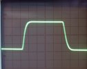
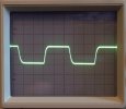
Here is a 10Khz square wave - remarkably it stays consistent in the small signal right up to near full power

10Khz.jpg10Khz2.jpg

I'll measure the distortion at 50Hz shortly
 
Last edited:

al2002

Active Member
Joined
May 18, 2016
Messages
275
Likes
233
I'd love to know more about the output transformer used, and whether the transformer design is an Arthur Radford or something new. Also, what distortion is like at 50Hz and at different power levels.

There was a design published in Wireless World many years ago converting a Williamson amp to SS driver retaining the valve outputs but the results were nothing as good as these here, so very interesting.

S
April 1976. WW published some othe SS drivers in the 1990s.
 

Tom C

Major Contributor
Joined
Jun 16, 2019
Messages
1,512
Likes
1,383
Location
Wisconsin, USA
I see from your web site that at least one of your other amps has selectable output impedance, from 4 to 16 ohm. These measurements were made into an 8-ohm load, but was the selected output impedance 8 ohm or something different?
 
OP
Radford Revival
Joined
Sep 7, 2023
Messages
11
Likes
31
I see from your web site that at least one of your other amps has selectable output impedance, from 4 to 16 ohm. These measurements were made into an 8-ohm load, but was the selected output impedance 8 ohm or something different?

Indeed, the measurements were done into 8 ohms from the secondary set to be matched to 8 ohms. So the smaller amps I make have a switch on the rear which reconfigures the output transformer secondary for those impedances - it's not just a simple switch to chose a tap, the entire secondary is used for each setting. These amps are a modern recreation of a mid 60s design.

This new design that isn't mentioned on the website (which badly needs updating) does a similar thing, but with a user replaceable module which you screw in internally.
 

Tom C

Major Contributor
Joined
Jun 16, 2019
Messages
1,512
Likes
1,383
Location
Wisconsin, USA
I would expect, then, to be able to set the output impedance to 4-ohm, and retest, keeping the actual load at 8 ohm, and get even better distortion statistics, at the expense of lower output. Is that the case here?
Indeed, the measurements were done into 8 ohms from the secondary set to be matched to 8 ohms. So the smaller amps I make have a switch on the rear which reconfigures the output transformer secondary for those impedances - it's not just a simple switch to chose a tap, the entire secondary is used for each setting. These amps are a modern recreation of a mid 60s design.

This new design that isn't mentioned on the website (which badly needs updating) does a similar thing, but with a user replaceable module which you screw in internally.
 
OP
Radford Revival
Joined
Sep 7, 2023
Messages
11
Likes
31
I would expect, then, to be able to set the output impedance to 4-ohm, and retest, keeping the actual load at 8 ohm, and get even better distortion statistics, at the expense of lower output. Is that the case here?

Absolutely - in fact the transformer in this case can be set for a more modern 8, 4, and 2 ohms.
 

SSS

Senior Member
Joined
Jan 12, 2023
Messages
319
Likes
202
Location
Germany
Absolutely - in fact the transformer in this case can be set for a more modern 8, 4, and 2 ohms.
Althoug I like and restore tube amps I wonder what the benefit is here using output tubes and an output transformer when anyway solid state devices work on frontend and tube drive?
 
Top Bottom