
v1adpetrov2
Member
- Joined
- Sep 24, 2022
- Messages
- 84
- Likes
- 83
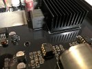
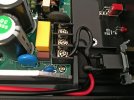
I received my copy of TPA3255XLR by mail!
The autopsy revealed that I also have an updated v1.5, just like ICIETDYIEUR.
_original_01.jpg")
_original_03.jpg")
_original_07.jpg")
_original_08.jpg")
_original_12.jpg")
_original_14.jpg")
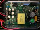
Output ripple SMPS without connected amplifier board: near 340mV, which is bad enough.

Ripple on the connected amplifier board, which is already catastrophically bad.
.png")
We will figure out why the amplifier board adds such huge ripples to, to put it mildly, a low-quality power supply.
1. I removed the cooling radiator from the TPA3255 chip: half of the legs are covered with a huge amount of thermal paste.
This caused the excitation of the chip and the generation of high-frequency interference.
And cleaned the thermal paste and washed the chip with isopropyl alcohol.
At the same time I made two modifications:
- replaced the 30 kOhm resistor with 10 kOhm, which raised the frequency of the modulator from 450 kHz to 600 kHz.
- shunted a 220uF/63V electrolytic capacitor to power the chip with a 1nF/100V film capacitor to remove some of the high-frequency ripples.
_mod_the_front_side_01_(small).jpg")
_mod_the_reverse_side_01.jpg")
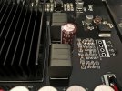
The manufacturer again saved and install 1uF capacitors instead of WIMA 2.2uF film capacitors.
Added four 1uF capacitors to increase the total capacity to 2uF:
_original_15.jpg")
_mod_the_reverse_side_02.jpg")
I carefully applied a new thermal paste to the TPA3255 chip and returned the cooling radiator to its place.
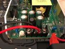
And started the main modification - the addition of a resistive-capacitive load to filter ripples and provide peak power surges to heavy speakers.
Many years ago, I developed a filter-booster "snowflake" for small-sized amplifiers with an external power supply and successfully used it in various projects.
.jpg")

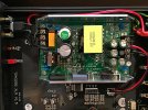
According to the same principle, I added four 2200uF/63V electrolytic capacitors and one 0.015uF polypropylene capacitor to lower the ESR.
And I added two 0.1 Ohm/20W resistors to the plus and minus terminals between the power supply and the amplifier board.
_mod_the_front_side_03.jpg")
Without resistors, the power supply unit, when turned on, tries to charge a capacitor bank with a capacity of almost 10,000 Muf, does not withstand peak values of current consumption and protection is triggered.
Plus, some of the high-frequency oscillations from SMPS are quenched on these resistors.
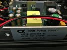
The variable resistor in the power supply easily allows you to change the output voltage from 32 V to 49 V.
Some users have noticed that when the power supply voltage levels are close to the maximum, TPA3251 and TPA3255 sound better than when lowered.
TPA3251 from 32 volts and above,
TPA3255 from 40 volts and above.
Although this is of course subjective.
For myself, I set the voltage to 42V, the benefit of the converter chip up to 12V LM2575HVS-12 works with an input voltage up to 60V.
_original_11.jpg")
Ripple on the connected amplifier board, after all modifications.

Vpp=180mV.
Much better already!
Linear power supplies with a toroidal transformer usually have output ripples of 100 - 120 mV.
A better power supply can be achieved if you replace the standard SMPS with another power supply with the PFC function.
For example, like this!
The autopsy revealed that I also have an updated v1.5, just like ICIETDYIEUR.
Output ripple SMPS without connected amplifier board: near 340mV, which is bad enough.
Ripple on the connected amplifier board, which is already catastrophically bad.
We will figure out why the amplifier board adds such huge ripples to, to put it mildly, a low-quality power supply.
1. I removed the cooling radiator from the TPA3255 chip: half of the legs are covered with a huge amount of thermal paste.
This caused the excitation of the chip and the generation of high-frequency interference.
And cleaned the thermal paste and washed the chip with isopropyl alcohol.
At the same time I made two modifications:
- replaced the 30 kOhm resistor with 10 kOhm, which raised the frequency of the modulator from 450 kHz to 600 kHz.
- shunted a 220uF/63V electrolytic capacitor to power the chip with a 1nF/100V film capacitor to remove some of the high-frequency ripples.
The manufacturer again saved and install 1uF capacitors instead of WIMA 2.2uF film capacitors.
Added four 1uF capacitors to increase the total capacity to 2uF:
I carefully applied a new thermal paste to the TPA3255 chip and returned the cooling radiator to its place.
And started the main modification - the addition of a resistive-capacitive load to filter ripples and provide peak power surges to heavy speakers.
Many years ago, I developed a filter-booster "snowflake" for small-sized amplifiers with an external power supply and successfully used it in various projects.
According to the same principle, I added four 2200uF/63V electrolytic capacitors and one 0.015uF polypropylene capacitor to lower the ESR.
And I added two 0.1 Ohm/20W resistors to the plus and minus terminals between the power supply and the amplifier board.
Without resistors, the power supply unit, when turned on, tries to charge a capacitor bank with a capacity of almost 10,000 Muf, does not withstand peak values of current consumption and protection is triggered.
Plus, some of the high-frequency oscillations from SMPS are quenched on these resistors.
The variable resistor in the power supply easily allows you to change the output voltage from 32 V to 49 V.
Some users have noticed that when the power supply voltage levels are close to the maximum, TPA3251 and TPA3255 sound better than when lowered.
TPA3251 from 32 volts and above,
TPA3255 from 40 volts and above.
Although this is of course subjective.
For myself, I set the voltage to 42V, the benefit of the converter chip up to 12V LM2575HVS-12 works with an input voltage up to 60V.
Ripple on the connected amplifier board, after all modifications.
Vpp=180mV.
Much better already!
Linear power supplies with a toroidal transformer usually have output ripples of 100 - 120 mV.
A better power supply can be achieved if you replace the standard SMPS with another power supply with the PFC function.
For example, like this!
Attachments
-
 BRZHIFI_Balanced_(TPA3255)_original_13.jpg289.4 KB · Views: 248
 -
 BRZHIFI_Balanced_(TPA3255)_original_02.jpg270.7 KB · Views: 224
 -
 BRZHIFI_Balanced_(TPA3255)_original_04.jpg442.4 KB · Views: 216
 -
 BRZHIFI_Balanced_(TPA3255)_original_05.jpg400.2 KB · Views: 214
 -
 BRZHIFI_Balanced_(TPA3255)_original_06.jpg305.9 KB · Views: 206
 -
 BRZHIFI_Balanced_(TPA3255)_original_09.jpg568.4 KB · Views: 211
 -
 BRZHIFI_Balanced_(TPA3255)_original_10.jpg527.6 KB · Views: 329
Last edited:
")
_original_16.jpg")
_mod_the_front_side_04.jpg")


_original_17.jpg")
_original_18.jpg")

.jpg")
_original_11.jpg")
_original_19.jpg")
_original_20.jpg")
_original_21.jpg")
_original_21b.jpg")
_mod_the_front_side_05.jpg")
_mod_the_front_side_06.jpg")