• WANTED: Happy members who like to discuss audio and other topics related to our interest. Desire to learn and share knowledge of science required. There are many reviews of audio hardware and expert members to help answer your questions. Click here to have your audio equipment measured for free!

Breeze TPA3255 XLR Balanced Amplifier TearDown : DIP8 Op Amps.

ICIETDIYEUR

Member
Joined
Sep 27, 2022
Messages
90
Likes
42
Location
FRANCE
It's all about compromise !

What do you think of this change ? ->

Alim générale 12 Volts.jpg
 

SMen

Active Member
Joined
Jan 2, 2022
Messages
110
Likes
38
View attachment 237717
According to the datasheet, the TPA3255 will also work at 18 V supply voltage.
Another thing is that at 18V and at 50V the output ripples of power supply will be almost the same. So at 18V, the signal-to-noise ratio at the output will be worse than at 50V.
That's all the math... ;)
That is interesting that the power supply noise will remain pretty much the same. As I repeat - I am not an engineer, so thank you for explaining.

I'm using a Gophert into another 3255 which apparently has ripple & noise at a very low at <30 mVp-p and this was audibly better than another enclosed unit when I compared. I'm tempted to bypass the existing unit and plug this other unit in! Maybe an allo capacitance multiplier for good measure. :D
Yes I'll lose the power, but it is a comparison I could do. For me just swapping in the OPA1656 was impactful, and reading ICIETDYIEUR's point about the impedance relating to OP amp interesting too. I think I would stop at sorting out the ripple. Mind you - I am using my unit on full volume with external volume controls, and no audible noise or hiss. It's impact on the music though I cannot know.

That's the thing about this forum people sometimes forget. Listening is OK :) (this is completely unrelated to any of your posts by the way) - just an additional thought as I write.
 

SMen

Active Member
Joined
Jan 2, 2022
Messages
110
Likes
38
v1adpetrov2 said:


View attachment 237717
According to the datasheet, the TPA3255 will also work at 18 V supply voltage.
Another thing is that at 18V and at 50V the output ripples of power supply will be almost the same. So at 18V, the signal-to-noise ratio at the output will be worse than at 50V.
That's all the math... ;)

Actually one other question - what is the signal-to-noise at the output? Are you guys able to replicate Amir's SINAD measure?
The Allo Volt D I have is 84db. The Aiyima A07 is 83db.
View attachment 237717
According to the datasheet, the TPA3255 will also work at 18 V supply voltage.
Another thing is that at 18V and at 50V the output ripples of power supply will be almost the same. So at 18V, the signal-to-noise ratio at the output will be worse than at 50V.
That's all the math... ;)
Actually one other question - what is the signal-to-noise at the output? Are you guys able to replicate Amir's SINAD measure?
The Allo Volt D I have is 84db. The Aiyima A07 is 83db. Yours would be after your modifications possibly but Icediyeur has an unmodified'ish one.

Not being greedy or anything ;-)
 

gnat_leader

Member
Joined
Oct 15, 2022
Messages
96
Likes
46
Hi amigos )

As promised, I am sharing some spec and pictures about the new Breeze Audio TPA3255 amplifier.
This is the only full balanced finished amp that I found for less than $200 )

The amp comes in an black aluminum case of modest size but seems robust however.
In the front plate you will find the RCA / XLR inputs selector with that motorized volume pot and the ON/OFF switch
I am still wondering why spending so much money on a motorized potentiometer since the amp doesn't have a remote...

The speakers banana connectors are OK and seem solid.
The XLR connectors are OK as well with a secure clip. RCA inputs are conventional
I do not observe any play on the volume knob and nothing to complain with.
You can see that the inside speaker cables and PSU to module cables are directly soldered to the PCB. (no JST connector here)

Safety is important: the amplifier is properly grounded ) Nice for a Chinese amp. )
BUT :the neutral and the phase were reversed... I corrected it )

Little mod I made :

- Update OP amps > OPA2210 (crazy op amps, give a try really !)
- Twisted the 220V cables
- Reversed the Neutral / Phase properly
- Insulated the PSU to module 36V cable
- added ferrites on the speaker cables
- added copper film to the transformer core

Listening test still in progress. But after 1 hour I can say; dead silence (even with my ears glued to the speakers) I only tested the XLR inputs with my Gustard A18 DAC.
The OPA2210 definitely worth trying! as good of the OPA1656 in term of Soundstage but with the best of the OPA1692. This super BETA Bipolar OP amps is really fast with a very low DC offset. The amplifier sounds great and very loud with the volume @ 30%. I tried to turn the volume @Max, it remains ultra silent, good point here.
For the rest, I can't say too much more, it's too early....

NB : I ve been testing many OP amps all Genuine from Mouser : OPA1622 / 1656 / 1612 / 1692 / 2210


TPA3255 MODULE :

WIMA MKS Caps (next to the volume pot) = 2U2J63 2.2uf / 63V
Electrolytic SMD Caps next to the OP amps = 220uf / 16V
Panasonic FC caps between inductors : 50V / 220uf
Switching Voltage Regulator = TI LM2575S-12
Electrolytic SMD Caps next to the Voltage regulator = 220uf / 16V
Power caps next to XLR inputs : 470uf / 50V
Polypropylene Film Capacitors : MKP10 / 0.1-250
Hongfa Relay = HFD4 / 5-S
Sagami Inductors
Volume pot : Alps Motorized Quadrirotor RK168 100K 100KAX4

PSU :

SMPS PSU 36V / 9.5A @342W
Epsilon 400uf / 400V x2
United Chemicon 1000uf / 50V x 4
Stable @ multimeter !


I just noticed that the pics in the OP show the circuit board is V1.1 and the one being sold shows V1.5 (pic below)
Was this already talked about in this thread, what if any the difference is? ... if anyone knows.
edit: well I guess I can start off with the obvious thing, the audio circuit board was extended left and now the speaker binding posts connect to the PCB versus the wires used in V1.1. Is the change audible?... I'd guess not.
 

Attachments

  • v1.5-A1394ae3ade594b7389f51fca82109ed1f.png
    v1.5-A1394ae3ade594b7389f51fca82109ed1f.png
    2.5 MB · Views: 85
Last edited:

ICIETDIYEUR

Member
Joined
Sep 27, 2022
Messages
90
Likes
42
Location
FRANCE
Yes but:

36 Volts x 9,5 Ampères = 342 VA (~ Watts)

So = 350W

There is a mistake on the table -> it's only written 4,2A !

In addition, concerning the amplifier: I can tell you that the available power is really present :D


Don't worry

Regards ;)
 
Last edited:

gnat_leader

Member
Joined
Oct 15, 2022
Messages
96
Likes
46
Yes but:

36 Volts x 9,5 Ampères = 342 VA (~ Watts)

So = 350W

There is a mistake on the table -> it's only written 4,2A !

In addition, concerning the amplifier: I can tell you that the available power is really present :D


Don't worry

Regards ;)

ok. now I see the V1.5 subject was talked about before here.
 

ICIETDIYEUR

Member
Joined
Sep 27, 2022
Messages
90
Likes
42
Location
FRANCE
Well yes...

We are in the same subject, you did not have to follow.
It is important to take a topic from the beginning to fully understand what we are talking about.
This avoids questions for nothing ;)
 

gnat_leader

Member
Joined
Oct 15, 2022
Messages
96
Likes
46
Yes but:

36 Volts x 9,5 Ampères = 342 VA (~ Watts)

So = 350W

There is a mistake on the table -> it's only written 4,2A !

In addition, concerning the amplifier: I can tell you that the available power is really present :D


Don't worry

Regards ;)

I have 97db sensitive speakers. I'm not worried. ;)
 

ICIETDIYEUR

Member
Joined
Sep 27, 2022
Messages
90
Likes
42
Location
FRANCE
Then a push-pull of EL84 will be enough :p
 

v1adpetrov2

Member
Joined
Sep 24, 2022
Messages
84
Likes
83
Actually one other question - what is the signal-to-noise at the output? Are you guys able to replicate Amir's SINAD measure?
The Allo Volt D I have is 84db. The Aiyima A07 is 83db. Yours would be after your modifications possibly but Icediyeur has an unmodified'ish one.

Not being greedy or anything ;-)
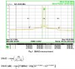
Unfortunately, I don't have hardware+software like amirm (APx500) that creates such great measurement graphs.
But in the near future I will try to make several measurements of my 3255XLR instance and calculate SINAD using the formula.
SINAD_formula_.jpg
And you are right about the main thing: everyone decides for himself what parameters of his equipment he wants to achieve and how much money to spend on these modifications.
Let's not be too greedy... :)
 
Last edited:

SMen

Active Member
Joined
Jan 2, 2022
Messages
110
Likes
38
TPA3255 3251 3221 or 3116? which sounds more like an EL84?
Reading about FET input OP's - many say they can be slightly valve like.
Subjectively, the OPA1656 for me is both more detailed and expansive than the stock chip (impressively so), but with a quality that ever so slightly gives a sense of "ease".

More objectively, and I'm going to link to a quote from Amir here discrete op amps review page 1. In response to someone saying that "subjective is not what this site is about"
Amir said:

"We are actually. It is just that the subjective testing needs to be controlled and be within the cycle of our short-term memory. I don't have two amps with each opamp in them to be able to switch instantly to hear small differences. Failing that, we can go by the measurement differences which are very small and likely below threshold of hearing of most people".


The BRZHifi 3255's lid - once you have navigated the glue (thank you ICIETDYIEUR here too)- lifts off by unscrewing the top four screws. This makes it incredibly easy to unplug (just reminding myself :)), swap in OP amps, listen, and swap back.

With TPA3255 the changes are quite clear to me, and then also with extended listening with records I know like the back of my hand. If I had the skills or knowledge, I would try to measure why...

The other thing I would note from the above thread, is that the stock op amp was the TI OPA1612A - which if my reading is correct, is better for low impedance circuits than the OPA1656 (see ICIETDYIEUR's comment about impedance, where he suggests the OPA1656 may well be a good match here for the higher impedance circuit ...) - Also, the stock TI OPA1612A in the above 'high end' example perfectly well takes on the discretes ...

So I am finding it very interesting ...

Interesting also that you found the power supply. I wonder if that 360mV is the last column is the ripple ... if so, that is very honest of them! v1adpetrov2 measured 340! :D
 
Last edited:

SMen

Active Member
Joined
Jan 2, 2022
Messages
110
Likes
38
Unfortunately, I don't have hardware+software like amirm (APx500) that creates such great measurement graphs.
But in the near future I will try to make several measurements of my 3255XLR instance and calculate SINAD using the formula.
View attachment 237822
And you are right about the main thing: everyone decides for himself what parameters of his equipment he wants to achieve and how much money to spend on these modifications.
Let's not be too greedy... :)
Calculating the SINAD would be seriously interesting - not sure if we can get a before and after. Great thread.
 

ICIETDIYEUR

Member
Joined
Sep 27, 2022
Messages
90
Likes
42
Location
FRANCE
Hi everyone :)

@v1adpetrov2:

What do you think about replacing the 220μF polymer with an electrochemical 470μF ? ->

Alim générale 12 Volts.jpg


I also redid suggestions for more readable capacitor bank locations:

-MOD 1

POS 1.jpg


Total = 10 000 µF

-MOD 2

POS 2.jpg


Total = 10 000 µF

-MOD 3 (20 'HP' for 18 inches speakers :eek:)


POS 3 (20 HP for 18 inches).png


Total = 20 000 µF o_O :cool:

What do you think ?

What would be your choice ?

Regards ;)
 
Last edited:

Doodski

Grand Contributor
Forum Donor
Joined
Dec 9, 2019
Messages
21,539
Likes
21,821
Location
Canada
Hi everyone :)

@v1adpetrov2:

What do you think about replacing the 220μF polymer with an electrochemical 470μF ? ->

View attachment 237902

I also redid suggestions for more readable capacitor bank locations:

-MOD 1

View attachment 237904

Total = 10 000 µF

-MOD 2

View attachment 237906

Total = 10 000 µF

-MOD 3 (20 'HP' for 18 inches speakers :eek:)


View attachment 237908

Total = 20 000 µF o_O :cool:

What do you think ?

What would be your choice ?

Regards ;)
My choice would be to get this amp connected to a oscilloscope and view the power supply output to determine if 10,000+ micro Farad is required. Otherwise have fun and put them where you can. If you drastically increase the power supply smoothing capacitance with a switching power supply like you have here you may experience issues with the power supply operation. The only way to know is to try it.
 

v1adpetrov2

Member
Joined
Sep 24, 2022
Messages
84
Likes
83
1. What do you think about replacing the 220μF polymer with an electrochemical 470μF ? ->

2. I also redid suggestions for more readable capacitor bank locations:
-MOD 1 Total = 10 000 µF
-MOD 2 Total = 10 000 µF
-MOD 3 Total = 20 000 µF o_O :cool:

What do you think ?
What would be your choice ?
1. The dataset LM2575HV recommends using a 330μF capacitor. Therefore, you can easily change to 470μF without hesitation...
BRZHIFI_Balanced_(TPA3255)_original_22.jpg
2.
I'm afraid that the load of 20000μF for the current power supply will be too large.
The main thing here is to stop in time!
According to the location, I like Mod 1 more.
The length of the wires from the capacitor bank to the power input point is very important.
The shorter and thicker they are, the less there will be third-party high-frequency ripples and power interference.
I again strongly recommend installing an additional 0.015μF polypropylene capacitor directly at the power input point.
BRZHIFI_Balanced_(TPA3255)_mod_the_front_side_05b.jpg

Here is how, for example, the power supply for Hi End DAC looks like:
power_supply__002b.jpg Or like this: BRZHIFI_Balanced_(TPA3255)_original_23.jpg
Polypropylene capacitors are never enough! :)
 
Last edited:

dfuller

Major Contributor
Joined
Apr 26, 2020
Messages
3,390
Likes
5,223
Reading about FET input OP's - many say they can be slightly valve like.
Erm, no, not really... The only thing they have in common is a super high input impedance.

What do you think about replacing the 220μF polymer with an electrochemical 470μF ? ->
Why? What benefit would it bring?

My choice would be to get this amp connected to a oscilloscope and view the power supply output to determine if 10,000+ micro Farad is required. Otherwise have fun and put them where you can. If you drastically increase the power supply smoothing capacitance with a switching power supply like you have here you may experience issues with the power supply operation. The only way to know is to try it.
Exactly. This isn't a linear supply where "more capacitance equals more better".
 
Last edited:

SMen

Active Member
Joined
Jan 2, 2022
Messages
110
Likes
38
Erm, no, not really... The only thing they have in common is a super high input impedance.


Why? What benefit would it bring?
Erm ... people do say this ... I was saying something different ...

Why not reply to two posts with two replies?

Surely "replacing the 220μF polymer with an electrochemical 470μF" is actually the question? What benefit and why / why not?

Maybe try it in French :)
 
Top Bottom