• WANTED: Happy members who like to discuss audio and other topics related to our interest. Desire to learn and share knowledge of science required. There are many reviews of audio hardware and expert members to help answer your questions. Click here to have your audio equipment measured for free!

At what frequency does sidemounted bassdrivers become a trouble for sound location ?

At what frequency does sidemounted bass drivers become a trouble for sound location ?

  • 1. 500 Hz

    Votes: 2 5.6%
  • 2. 400 Hz

    Votes: 3 8.3%
  • 3. 300 Hz

    Votes: 5 13.9%
  • 4. 200 Hz

    Votes: 6 16.7%
  • 5. 150 Hz

    Votes: 13 36.1%
  • 6. 100 Hz

    Votes: 2 5.6%
  • 7. 80 Hz

    Votes: 5 13.9%

  • Total voters
    36

Rick Sykora

Major Contributor
Forum Donor
Joined
Jan 14, 2020
Messages
3,651
Likes
7,407
Location
Stow, Ohio USA
Add in that I recall it also may depend on how clean the bass is…

Recall reading that our hearing can localize high order harmonic distortion.
 

tmuikku

Senior Member
Joined
May 27, 2022
Messages
304
Likes
341
Looks as though the best answer here is it depends on speaker location.

Perhaps the poll should be updated to be clear that there may be more than one frequency. Or may be what worst case is?
I'd say size of the speaker, in general, would affect the crossovers used and so on. Also, positioning the speaker would change distance to all boundaries and affect perceived sound.

Referred earlier that single reflection is just one of many, and thus not probably very significant except if perception is such that makes it somehow particularly audible thing. Not sure if it happens on a three way speaker bass bandwidth. CTA2034-A bundless the reflections into PIR and DI and sound power, which I suppose is more important than location of a woofer as a detail. I mean as long as these "average" metrics are achieved nicely the woofer is about at the right place physically and with roughly appropriate signal processing? Or is it?:)

edit.
I forgot to write what I'm after with all the posts :D As the woofer location doesn't seem to make much difference, to me, I would like to know if there is any real downsides, or benefots, in a system context. I mean, if there is a side woofer or two, whats the most important audible difference and why compared to just having woofer on front?

I can imagine many things the sidewoofer position enables, stuff that should make better sound, but not sure if it actually happens. Never heard such speaker so, no opinion about.
 
Last edited:

tmuikku

Senior Member
Joined
May 27, 2022
Messages
304
Likes
341
Recall reading that our hearing can localize high order harmonic distortion.
You can do rough reasoning on this subject. I'm not sure such thing is concern in a properly sized 3 way system but lets take some arbitrary two way speaker for a quick thought experiment.

There is cone break up on our woofer, say at 2kHz, having 10db boost on axial response and 10db dip otherwise on the listening window. Now, the kick bass comes in and makes some harmonic distortion happen in the driver since there is great excursion. Any distortion products, harmonics, that happen in the driver motor for example get now 10db boost on-axis around the 2kHz, around the crossover, and might be first hint of distortion you hear as you feed more power to the speaker if you happen to listen on axis, distortion beaming. Not sure how this would affect localization :D Anyway, example of distortion emitted differently as the direct sound.

Or another quickie, subs, lets take 80Hz is not localizable as its taken some kind of standard for movies LFE, crossover there. 2nd harmonic at 160Hz, third, 240Hz, yeah, fourth 320Hz for sure. These would be rather omni for home subs. Better to scale up the cone area to suppress harmonic distortion, if localization is a concern :) Or use some acoustic low pass.
 
Last edited:

Rick Sykora

Major Contributor
Forum Donor
Joined
Jan 14, 2020
Messages
3,651
Likes
7,407
Location
Stow, Ohio USA
You can do rough reasoning on this subject. I'm not sure such thing is concern in a properly sized 3 way system but lets take some arbitrary two way speaker for a quick thought experiment.

There is cone break up on our woofer, say at 2kHz, having 10db boost on axial response and 10db dip otherwise on the listening window. Now, the kick bass comes in and makes some harmonic distortion happen in the driver since there is great excursion. Any distortion products, harmonics, that happen in the driver motor for example get now 10db boost on-axis around the 2kHz, around the crossover, and might be first hint of distortion you hear as you feed more power to the speaker if you happen to listen on axis, distortion beaming. Not sure how this would affect localization :D Anyway, example of distortion emitted differently as the direct sound.

Or another quickie, subs, lets take 80Hz is not localizable as its taken some kind of standard for movies LFE, crossover there. 2nd harmonic at 160Hz, third, 240Hz, yeah, fourth 320Hz for sure. These would be rather omni for home subs. Better to scale up the cone area to suppress harmonic distortion, if localization is a concern :) Or use some acoustic low pass.

Not sure where I read, but also may have been pure tones vs real sounds. Will see if I can dig it up.
 

tmuikku

Senior Member
Joined
May 27, 2022
Messages
304
Likes
341
Hi, impulsive writing today from my part, re-read the thread and most of it was already there, my apologies for that.

Well, the subject interests me as I've been quite concerned about singular early reflections, as concerned a hobbyist can be, but after pondering about flutter echo most of the concerns were flushed away. Flutter echo is easily one of the most audible and easily recognizable issues in home acoustics, rarely mentioned and fore xample the early reflections get much more attention. While singular first reflection can be of distract the flutter echo consist of reflections originated towards multiple angles and seems to be most audible as kind of high frequencies and really takes away intelligibility. This puts singular reflections into a perspective that while they would matter some to perceived sound, in various ways, certainly its is not significant issue, not significant distraction like flutter echo is. More over, if checking out path lengths of all the first reflections through all room boundaries simultaneously as interference they would all have first big dip below 1kHz, usually piling up making single wide suckout practically carving all the mids out. Attenuating / shifting one of the reflections doesn't affect the great dig about at all, still measurement at listening position looks more like the power response well, heres the background for my skepticism, and view that position of a woofer doesn't matter as long as system DI and ERDI ends up about nice. I don't know much about audibility of the very early reflections, interesting topic with lots of mystery behind, although there is studies about the audibility.

ctrl, I kind of caught on your words of "disturbing" and "significant" effect of early reflections but cannot reason why that would be and started poking on it. Sorry about that, I could have just asked what have you experienced on the subject, and read all the "might"s and" could"s as well :)

Well, to give some content for the post here is quick thought experiment on flutter echo: go to a room with naked parallel walls and clap your hands. Perhaps 100ms or more flutter duration per clap, quite typical, several places in this apartment where its quite audible. 100ms is about 34m distance for sound in air. In a 5m x 5m x 2.5m room, considering only two parallel walls and clapping in between, within 100ms one hears roughly 14 reflections, up to 7th order from each wall, both bouncing between the two walls. Between floor and ceiling all early reflections up to 14th order would arrive within the 100ms. Count in more than two naked surfaces and the number of reflections within that 100ms skyrockets, makes it very audible phenomenon. Its amazing if hearing system would be still able to distinguish effects of some singular events while all this is happening, between direct sound and all the reflections. But hearing system is quite amazing isn't it :)
 
Last edited:

ctrl

Major Contributor
Forum Donor
Joined
Jan 24, 2020
Messages
1,640
Likes
6,281
Location
.de, DE, DEU
ctrl, I kind of caught on your words of "disturbing" and "significant" effect of early reflections but cannot reason why that would be and started poking on it. Sorry about that, I could have just asked what have you experienced on the subject, and read all the "might"s and" could"s as well
It's always okay to ask questions, and I'm sometimes way off base with my assessments. Your comments have encouraged me to delve a little deeper into the subject.

Regarding the first-order lateral reflection (with woofer on the front baffle, two lateral woofer and one lateral woofer), I still made a few BEM simulations that surprised me quite a bit.

Will post something about this tomorrow.
 

ctrl

Major Contributor
Forum Donor
Joined
Jan 24, 2020
Messages
1,640
Likes
6,281
Location
.de, DE, DEU
Let us consider the three cases
A) woofer on front
B) woofer on each cabinet side
C) woofer on one cabinet side
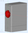
in detail. To be able to really compare the cases, BEM simulations were created for all cases (6.5'' woofer, WxHxD is 20cm x 50cm x 40cm, woofer height 32.5cm, similar to post#55):
A) 1677098272240.png B) 1677098316539.png C) 1677098372344.png
The listening position was always 2m away at the height of the woofer in z-direction (corresponds to 0°, blue line in the images).

In the BEM simulation with one side woofer the listening axis is not centered (that would have been too much effort to change). Therefore, always add a small "error" when making comparisons with simulation C.

One of my assumptions was that one of the three cases would have advantages when considering the first order reflection from the sidewall.
The delay differences are not dramatic, but I assumed that the sound pressure levels on-axis and at 90° would be significantly different for the three cases. With an advantage for C. The matter is not that simple after all. For example my listening room with double sided woofer and inward pointing side woofer (first order side wall reflection in red):
B)1677099677901.png C)1677099661856.png


Simulation for all showed data is 20-1500Hz.

Let us first consider the normalized sonograms for all three cases:
A)1677099939820.png B)1677100199520.png C)1677100027600.png
You can already see that Case C is going to be interesting ;)

When the speaker is aimed at the listener, the sidewall reflection corresponds to an angle of 70-90° (as a proxy we use 90°). This is difficult to see in the sonograms, so we compare the normalized on-axis FR with the 90° FR for all three cases.
I was very surprised by the results.

The red curve corresponds to the sound pressure level on-axis and turquoise, blue and green corresponds to the 90° SPL of the three cases.
1677100545622.png

We probably have to subtract 1-2 dB from the green curve (because the listening axis was not centered), but the SPL is still the highest there in the relevant frequency range 100-350Hz compared to the on-axis FR.

Thus, the side reflection in case C would have the highest SPL at the listening position (we don't want that) - I was totally wrong with my assumption :facepalm: (It's because the on-axis SPL is very low).
The 90° FR is most uniform compared to the on-axis FR in case B when a woofer is placed on each side of the cabinet.

If we look at the polar diagram for all three cases at 250Hz, it also becomes clear again why case C is not so a good idea (even if you subtract 1-2dB at 90°). Further that case B has small advantages over the "normal" arrangement of the woofer on the baffle front (if the crossover frequency is not chosen too high), but also radiates significantly more sound to the rear:
1677101399432.png


As an alternative to the polar diagram, we can also look at the sound field around the speaker. For our three cases on a horizontal surface with about +-0.9m in x- and z-direction, at a frequency of 200Hz at woofer height:
1677104542908.png 1677104577804.png 1677104596761.png
Here you can see very nicely from the colors how much lower the SPL on-axis is with a single side woofer, compared to a front woofer.

Note: These are my first BEM simulations of side-placed woofers, so I have no comparisons to real projects and whether the simulation reflects reality well.
The statements apply only to the simulation made, with significantly different woofer positioning and cabinet size, there could be different results.
 
Last edited:

Rick Sykora

Major Contributor
Forum Donor
Joined
Jan 14, 2020
Messages
3,651
Likes
7,407
Location
Stow, Ohio USA
@ctrl, I may have missed, but gather your sims do not include any eq, phase or timing being applied to the side firing woofers?

P.S. suggest it is a fair assumption that most commercial (active) speakers with side firing woofers, are doing some tailoring of their output?
 
Last edited:

tktran303

Addicted to Fun and Learning
Forum Donor
Joined
Mar 27, 2019
Messages
686
Likes
1,222
I come with SPL data.

During investigation for dual opposed 8" woofers x 2, for a slimmer bass bin (pictured below).
ie. Right lower bass bin cabinet in MDF with 4 woofers in total, 2 on one side (right most that you can see), 2 on the other left side (that you can't see).

Pros- slimmer than dual 12" woofers (speaker on the left)
Cons- ?any


oblique.jpeg front.jpeg

Let's investigate directivity.

Measurement mic height 2.4m
2.83V drive level @1m.

Conditions: 31C; humidity 68%
(Heat wave for you guys probably but just another day in Northern Australia)

Black arrow represents on-axis (where microphone (not pictured ) was)

hor 0.jpeg


Horizontal 90 degrees:


hor 90.jpeg


Meaurements from 20Hz to 1KHz exported to VituixCAD2, from on axis, to horizontal 90 degrees off axis, in 10 degree steps.

a) As a polar map, normalised to on axis.

1668176845858.png


b) Normalised: to chart lines:


Chart lines.png


Conclusion 1.

In twin dual opposed. the woofer is close enough to omnipolar, to about 300Hz.

Conclusion 2:
Rotate your woofers to face front or sideways, that's up to you. OTOH, perhaps your eyes can trick your ears (or brain)

Addit:
Concurs with virtually every measurement of boxed speakers on ASR. Notice the directivity up to 300Hz...
 
Last edited:

tmuikku

Senior Member
Joined
May 27, 2022
Messages
304
Likes
341
@ctrl, I may have missed, but gather your sims do not include any eq, phase or timing being applied to the side firing woofers?

P.S. suggest it is a fair assumption that most commercial (active) speakers with side firing woofers, are doing some tailoring of their output?
Hi,

You probably already know all info on this post, but I'll write something that might not be obvious for some readers, about how to kind of think about simulator graphs.

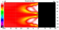
All sims ( in ctrl post, and my VCAD sims, usually on others ) use same "ideal transducer" in "ideal measurement environment" so any differences in the graphs are due to different physical construct, different acoustic environment for the transducer(s), a box and how transducer relates to the box. EQ affects frequency response to all directions and can "fix" issues for one axis only, while others usually get worse, with some room for wiggle. Normalized graphs show system response if the system was EQ:d flat to on-axis (or any angle that was chosen for normalization). This is maximum achievable performance you see on the normalized graph in this sense, and reveals if the construct is suitable for application you have in mind. If there is wiggle to a direction you don't like to have wiggle, then back to drawing board and make different construct that measures better, measures more like you'd want it to as designer in charge.

I would think your assumption is correct that manufacturers take account such things unless marketing team says otherwise, as would DIY people who measure/simulate more than axial response. Any of these configurations ctrl simulated are usable up to some frequency in a multiway speaker system context. One could make the side baffle smaller and the usable frequency goes up, and so on. Its about the physical construct and how dimensions relate to wavelength and the whole multi-way system needs to be knitted to work together.

Active system is almost mandatory for typical 3-way speaker with such side woofer(s) configuration, because delay is needed for the driver(s) on the front baffle as they are closer to the listener. Alternative to delay is to lower crossover low enough, but it would make expensive passive filter and ask for bigger mid on the front to maintain SPL capability. Makes the side woofer(s) a sub. DSP just enables nice fit for such design, or any other design for that matter :)
 
Last edited:

tmuikku

Senior Member
Joined
May 27, 2022
Messages
304
Likes
341
Since ctrl posted these nice graphs and I happened to already make similar box in VituixCAD here is some thoughts how to look the simulations and graphs:

If some one wants to experiment with such (any simple) configuration on their own without BEM skills/ slow computer its relatively easy with VituixCAD and gives nice approximation how a system behaves. Sound diffracting all around the box is missing in the VituixCAD diffraction tool responses, compare to ctrl BEM results to get hunch what that looks like. The "ridges" with increasing frequency and angle are due to sound around the box, sound around each side interfering with each other to various directions with varying path length difference, which is absent in VCAD sims. Some of these details are often absent in home measurements as well, due to short gating. These features are mostly above suitable crossover frequency, so its perfectly fine way to find out main features of such configuration like overall directivity on suitable pass band.
front-woofer.jpgtwo-side-woofers.jpgone-side-woofer.jpg
Screenshot from ctrl post for reference
screenshot-from-ctrl-post.png

The thing is, ideally, at least if ideal means very good performance in CTA 2034 graphs as metric, we'd wan't all kinds of wiggle and ripple from the responses go away. Basically "perfect speaker" would lose all the detail on the graphs, all we want is butter smooth slopes to any direction. If system has wiggle with simple VCAD sims with ideal drivers then we can reason the system performance won't be any better in reality or in BEM sim, and that there is still room to improve. In this sense vcad sims are perfectly fine guideline figuring out a loudspeaker design on high level before digging into details.

BEM sim shows detail close to reality and can simulate any size and shape, while VCAD is quite limited to transducers on flat baffles. But there is going to be some details that even the BEM sims don't show, like resonating panels. Both simulators are valid ways to get forward when one knows what one needs to be looking at one is perhaps more suitable than the other. When look on the details is needed BEM sim is required. Sometimes there is no need for great detail in which case simple sims and imagination can be quick path forward, to find out main features of the response which all the detail rides on. Both are very good learning tool for various phenomena visible on graphs.

edit.
For example, after setting up a sim in VCAD one can scroll with mouse wheel in real time to see how "width" of the box, distance between bipole sources, affects response and limits usable bandwidth. Two minutes for setup and 10 seconds of interaction to learn a lot which way to take the concept to zone in to a fitting system, what ever is it in ones mind :)
width-0.pngwidth-10.pngwidth-20.pngwidth-30.png
 
Last edited:

ctrl

Major Contributor
Forum Donor
Joined
Jan 24, 2020
Messages
1,640
Likes
6,281
Location
.de, DE, DEU
@ctrl, I may have missed, but gather your sims do not include any eq, phase or timing being applied to the side firing woofers?
It's the raw data of an "ideal woofer" in a cabinet (even the inner volume of the cabinet was not taken into account, since it is not relevant for the analysis).
When one woofer or a wired pair of woofers is simulated, "timing being applied" would not change the radiation, so the answer is no, the simulations do not use delay.

You could, of course, take the simulated data of the woofer and merge it with the data from a simulated midrange (in the same cabinet) in VCAD and then experiment with the relative delay of the woofer and midrange there.

P.S. suggest it is a fair assumption that most commercial (active) speakers with side firing woofers, are doing some tailoring of their output?
As @tmuikku said, any loudspeaker designer today, commercial or DIY, will use off-axis measurements in their development and will adjust the crossover for best results using tools like VCAD.

The OT wanted to know in advance what effects woofers placed on the cabinet sidewall can have and now probably has more data and nerdy details than he would have liked ;)


In twin dual opposed. the woofer is close enough to omnipolar, to about 300Hz.
Thanks for the real life data! This confirms that, in principle, the simulations provide realistic data. The cabinet dimensions and number of drivers are not comparable, but the basic radiation behavior is.

real life example versus BEM-Simulation example
1677147409844.png 1677148321527.png


[off-topic]
In this sense vcad sims are perfectly fine guideline. In reality there is going to be some wiggle or various reasons, that even the BEM sims don't show, like box resonances.
Wish that VCAD would support stepped colors and the default step size of 3dB in the sonograms, the current display is hardly interpretable ;)

Totally agree with you. If you are aware of the limitations of the simulation, they are a very helpful tool - VCAD in particular offers a great many features.

VCAD diffraction tool simulations and all other "simple" diffraction tools I know of don't use depth information (as already mentioned). There a cabinet with 10cm depth gives the same results as a 50cm cabinet.
In reality, however, these cabinets could differ significantly in radiation from about 200-300Hz upwards.

Screenshot of the screenshot in post#71, shows the missing "step" in radiation caused by cabinet depth when using VCAD.
1677148673887.png
 

Rick Sykora

Major Contributor
Forum Donor
Joined
Jan 14, 2020
Messages
3,651
Likes
7,407
Location
Stow, Ohio USA
@tktran303 thanks for sharing!

Might want to check those speaker cable connectors for ferro content though. ;)
 

abdo123

Master Contributor
Forum Donor
Joined
Nov 15, 2020
Messages
7,449
Likes
7,964
Location
Brussels, Belgium
@ctrl have you made any simple, honest to God, 3-way designs in the past that you were content with?

If so please let me know in a PM or via a thread here. Would love to see your take on something ''simple''.
 

tmuikku

Senior Member
Joined
May 27, 2022
Messages
304
Likes
341
Screenshot of the screenshot in post#71, shows the missing "step" in radiation caused by cabinet depth when using VCAD.
Hi,

jeah I referred the "steps" feature as "ridges". It is showing constructive and destructive interference from sound diffracting around all sides of the box toward a direction.

Pardon me nerding over it a bit more because I think we have some different views whats significant and what is not and would like to linger on it for one more post :D Its long off-topic post but hopefully helps anyone reading it to calibrate their importance scale, I'm trying to calibrate mine. Writing seems to be most effective way to think and learn, hopefully there is some thoughtful response, like thus far. Or request to move it somewhere else if it feels like nonsense :)

Alright, imagine yourself standing 2 meters away at 130deg angle for example, behind a speaker box. Imagine the box was pitch black and you'd see just the outline of the box, not the 3D shape of it. This outline is what radiates sound towards you. Sound is not originating from the outline but from one or multiple transducers on some side of the box, since we stand on the backside we can't see the transducer. Sound from a transducer propagates spherically to all directions and has quite some variation in path length to all points on this outline. Also path length from the outline to your location varies and you'd measure some kind of a wiggly frequency response, interference due to multiple paths around the box sound took to reach you. If you stood exactly behind the box at 180 deg, there would be less path length difference around opposing sides, which means only constructive interference up to quite high frequency, kind of less wiggle.

Basically the ridges, or steps, in the graphs would be there no matter what the shape of the system/box is as long as there is one. Even with a sphere there is path length difference around the sphere from transducer to various directions and some interference will occur. These effects due to bulk of the box causing path length difference appear mainly at 90deg off-axis and beyond, because very little sound diffracts all the way 360 degrees around the enclosure. Diffraction has two parts, the one that goes around a corner and back wave that emits at the corner. Interference that is within 90 deg, in and nearby listening window, are mainly front edge diffraction back wave interfering with direct sound, features off the front of the speaker, the baffle. Some interference is due to box back edge diffraction back wave as well, but magnitude of this is minor compared to front edge diffraction. Basically intensity of sound is strongest near the transducer, on the baffle, and attenuates beyond due to diffraction and extra path length. Hence features of front of the box, physical construct near the transducer, makes strongest effect on the response and features of backside of the box just ripples on it.

So, the more there is round overs on the box the less these "steps" are in amplitude. Diffraction amplitude gets reduced and the "steps" being interference between direct and diffracted sound reduce. Frequency where the interference appears depends on path length difference, dimensions of the construct, like depth of a box. Also transducers matter, they might beam forward and have less sound toward the edge to make these effects.

Takeaway is that the "steps", or "ridges", are there no matter what the construct is and they can be anticipated even if they were missing from the simple sims. Amplitude can be estimated from the shape of the construct, roundness of it, and frequency from the size of the construct. Since they are wiggle in the graphs, to any direction, they can't be utilized too effectively although there can be some benefit. For example increasing depth of the box moves destructive interference down in frequency towards some angle, which might affect how a speaker behaves with a room with some particular positioning and toe-in. While this is something one perhaps can and should exploit, if its exploitable for any particular application, its still minor effect, a side effect, of the system, its magnitude is smaller than what baflle edge diffraction does. For example, one cannot change trend of DI with box back shape but only a little, make dent to it. Adjusting size and shape of the baffle, or adding more transducers / sound sources (anywhere on the box) would change trend of DI much more, while the back of the box makes ripple on it. Ideally, all of it is optimized and plays nice together as a system. First step is to clean the listening window by rounding the front of the box and minding what comes from the back edge.

Don't get me wrong, there can be many db peaks and strong nulls from the backside shape that is not visible in simple VCAD sims, I agree its significant in the graphs. But I'm thinking they are not very significant in practice because as long as they are not on the listening window and they are toward arbitrary frequencies to arbitrary directions, wiggle and ripple here and there. What would be significant in my opinion is to get rid of the ripple altogether, or make them dips wide bandwidth. I'm not sure if something like 3db or 10db dip at 200Hz or 400Hz towards some early reflection would be audible, or make any difference which one it is, especially when it all changes if one moves a little and angle towards reflection changes. They'd probably be detrimental for perceived sound quality nevertheless, if they are detrimental in the first place. Perhaps -10db for multiple octaves to wide enough angle span would be audible to anyone, perhaps neutral or positive effect on perceived sound quality, perhaps detrimental. Before any of this we'd better be sure to have nice DI and power response, the average. Too coarse sim would hide details on this though, but as said one can anticipate them.

Here is the opportunity, if one knows what hearing system can detect and why, then in theory the box can be sized and shaped so that the ripple to some particular direction aligns so that hearing system doesn't think its detrimental to perceived sound quality at some particular listening spot. Any of it could also have positive, or neutral, effect for perceived sound quality though. Since I don't really know audibility of much of it I've reasoned safest thing to do is to consider this far off-axis ripple neutral or detrimental for perceived sound quality and try to design it away if possible. And this is "easy", round overs, small size or very big size, multi-way etc. wavelength vs. physical objects. In the end its about audibility, whats meaningful. Kind of basic stuff in the end, no need for too much sim detail although all of this is from playing with simulations and measured data done at home and done by others like the Klippel scanners. What I'm lacking is listening experiences of various things, I only have access to my own system and prototypes, which is slow progress. Hence what matters and what doesn't, for perceived sound quality, is of high interest.

BEM is nice, my patience can't stand the wait though, have to stay quarter symmetry. Or use VCAD and imagination, much faster :)

edit. wow, I could still edit this after many hours of posting. Fixed few typos and swapped some sentences for better.
 
Last edited:

kimmosto

Active Member
Joined
Sep 12, 2019
Messages
222
Likes
529
Wish that VCAD would support stepped colors and the default step size of 3dB in the sonograms, the current display is hardly interpretable ;)
I suggest you should read user manual or look context menu.
directivity_context.png
 

kimmosto

Active Member
Joined
Sep 12, 2019
Messages
222
Likes
529
I also think that name of the topic is wrong. Directivity index of symmetrical sidemounted woofer concept dives to zero dB or below quite soon below the lowest crossover so correct question would be "What is maximum frequency where DI of conventional box speaker (or cardioid at mid...high) can dive to zero dB or below?". Higher diving freq. than 100 Hz could sound obscure and can be very sensitive to distance to front wall. That is the main design flaw of Blade and LS60 concept imo. Those speakers must be located very far from front wall to avoid self evident problems due to DI=0 and strong reflections from the front wall. Low XO freq. enables using in-phase reflection at upper bass with quite short distance to front wall and below typical Schroeder frequency. DI dives to 0 dB at some frequency above the lowest octave with other than full range cardioids so location should be adjusted carefully anyway.

This speaker is 4-way with the lowest XO ~140 Hz. DI dives to 0 dB at ~110 Hz, and cardioidish range with help of symmetrical sidemounted woofers starts quite soon above the lowest XO. Responses are quite much different than Kef's design products.
1677408565736.png

1677409356052.png
 

Rick Sykora

Major Contributor
Forum Donor
Joined
Jan 14, 2020
Messages
3,651
Likes
7,407
Location
Stow, Ohio USA
I also think that name of the topic is wrong. Directivity index of symmetrical sidemounted woofer concept dives to zero dB or below quite soon below the lowest crossover so correct question would be "What is maximum frequency where DI of conventional box speaker (or cardioid at mid...high) can dive to zero dB or below?". Higher diving freq. than 100 Hz could sound obscure and can be very sensitive to distance to front wall. That is the main design flaw of Blade and LS60 concept imo. Those speakers must be located very far from front wall to avoid self evident problems due to DI=0 and strong reflections from the front wall. Low XO freq. enables using in-phase reflection at upper bass with quite short distance to front wall and below typical Schroeder frequency. DI dives to 0 dB at some frequency above the lowest octave with other than full range cardioids so location should be adjusted carefully anyway.

This speaker is 4-way with the lowest XO ~140 Hz. DI dives to 0 dB at ~110 Hz, and cardioidish range with help of symmetrical sidemounted woofers starts quite soon above the lowest XO. Responses are quite much different than Kef's design products.
View attachment 267615
View attachment 267622

Thanks for sharing Kimmo!

When you say the KEF Blade would have to be very far from front wall, could you be more specific? I find that many with larger dedicated listening spaces a will tolerate placing speaker further out into the room. Lacking dedicated space, many others often have to be more practical about it and locate speakers closer to the front wall.
 
Last edited:

kimmosto

Active Member
Joined
Sep 12, 2019
Messages
222
Likes
529
When you say the KEF Blade would have to be very far from front wall, could you be more specific?
Major dip or dip and hump due to 1st order front wall reflection is created in every location where side woofers are 300 mm or longer from front wall and XO > 350 Hz i.e. speaker is omni-directional due to symmetrical sidemounted woofer concept.
1677412760287.png


Severe problem can be faded out when distance to front wall and corner is so long that other reflections are able mix effect of the dominant boundary. This concept needs quite low XO freq. to be flexible for different kind of locations. Kefs are still omni at low mid which can produce warm and full-bodied sound balance, but obscure sound stage, bad timing and zero kick at low mid. Design could be beautiful, but it's still bad concept with too high XO.
 
Last edited:
Top Bottom