• WANTED: Happy members who like to discuss audio and other topics related to our interest. Desire to learn and share knowledge of science required as is 20 years of participation in forums (not all true). There are daily reviews of audio hardware and expert members to help answer your questions. Click here to have your audio equipment measured for free!

"Analysis" of cardioid speaker radiation via lateral slots - like D&D 8c

OP
C

ctrl

Major Contributor
Forum Donor
Joined
Jan 24, 2020
Messages
1,377
Likes
4,651
Location
.de, DE, DEU
Do you post any of your progress regarding your personal project?
In the case that the project will be finished at some point and will sound okay, probably yes.
But after more than three years of house renovation, my urge for DIY is severely tamed and the ordered replicator comes earliest Jan. 2557.
 

Biblob

Addicted to Fun and Learning
Joined
Sep 13, 2018
Messages
609
Likes
552
In the case that the project will be finished at some point and will sound okay, probably yes.
But after more than three years of house renovation, my urge for DIY is severely tamed and the ordered replicator comes earliest Jan. 2557.
You let me Google that, but I found it. It's a pity we don't have infinite time at our disposal. ;)
 

Biblob

Addicted to Fun and Learning
Joined
Sep 13, 2018
Messages
609
Likes
552
@ctrl regarding the R2 speaker-project, do you think using a cardioid design will negatively impact it's max SPL, using only a 5" inch driver? Could it reach 105 dB at 1m at 200hz, still?
Even when crossed around 200 hz it will reach it max excursion pretty quickly, I'd think. Erin found out that these SB Acoustics drivers don't really meet spec regarding their x-max.
 
OP
C

ctrl

Major Contributor
Forum Donor
Joined
Jan 24, 2020
Messages
1,377
Likes
4,651
Location
.de, DE, DEU
@ctrl regarding the R2 speaker-project, do you think using a cardioid design will negatively impact it's max SPL, using only a 5" inch driver? Could it reach 105 dB at 1m at 200hz, still?
Even when crossed around 200 hz it will reach it max excursion pretty quickly, I'd think. Erin found out that these SB Acoustics drivers don't really meet spec regarding their x-max.
This should not be a problem at all as far as drive excursion is concerned. However, the voice coil is unlikely to withstand a sound pressure level of 105dB for long.

As a rough estimate for the excursion and load of the 5'' driver at [email protected] free field:

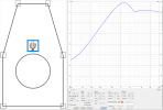
1. Here is the diffraction simulation of the Directiva r2 baffle as open baffle (the excursion of the drivers in speakers with slots is about the same as OB speaker):
1669074378065.png

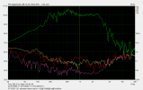
2. The combination of half-space frequency response of the driver on an infinite baffle and the diffraction correction to simulate free field conditions and an [email protected] high pass, results for [email protected] free field (used some 5'' driver, do not know off the top of my head which SB Accoustic driver it is):

1669074730311.png


A high thermal load for the voice coil of the 5'' woofer and an acceptable excursion at [email protected] free field.

More details on how to simulate the excursion of the driver, can be found here.
 
Last edited:

Biblob

Addicted to Fun and Learning
Joined
Sep 13, 2018
Messages
609
Likes
552
This should not be a problem at all as far as drive excursion is concerned. However, the voice coil is unlikely to withstand a sound pressure level of 105dB for long.

As a rough estimate for the excursion and load of the 5'' driver at [email protected] free field:

1. Here is the diffraction simulation of the Directiva r2 baffle as open baffle (the excursion of the drivers in speakers with slots is about the same as OB speaker):
View attachment 245185

2. The combination of half-space frequency response of the driver on an infinite baffle and the diffraction correction to simulate free field conditions and an [email protected] high pass, results for [email protected] free field (used some 5'' driver, do not know off the top of my head which SB Accoustic driver it is):

View attachment 245186

A high thermal load for the voice coil of the 5'' woofer and an acceptable excursion at [email protected] free field.

More details on how to simulate the excursion of the driver, can be found here.
That's not too bad actually! Especially the excursion, it isn't very high at those SPL levels. Although it will be at the limit of the driver.
The spec is 5mm if I recall correctly from the top of my head. Erin measured about half the distance from the manufacturer specs, so that would be around 3 mm.
 
Last edited:

fineMen

Addicted to Fun and Learning
Joined
Oct 31, 2021
Messages
891
Likes
361
Erin measured about half the distance from the manufacturer specs, so that would be around 3 mm.
If my recollection doesn't trick me, the limitation in excursion was due to the suspension, which isn't a major problem. It doesn't generate intermodulation, and HD is to a vast percentage masked by the musical content, which brings with it an overwhelming portion of harmonics (hence the name) anyway.

Do You aim to swamp an airport terminal with the speaker? I would argue that the combination of high force (acceleration) and high temperature could shut down a 'last call' announcement preliminary.
 

Savi

Member
Joined
Nov 15, 2020
Messages
59
Likes
44
Really interesting thread ! Thanks ctrl. I have two questions:
- you mentioned that slot area is often closed to cone area, do you have some link or paper which detail slot design rules (area and position) ?
- what would look the v and h sonogram of a front slot vented box (for instance a cube with woofer at the center and four slots around the woofer on front side) ?
 
OP
C

ctrl

Major Contributor
Forum Donor
Joined
Jan 24, 2020
Messages
1,377
Likes
4,651
Location
.de, DE, DEU
- you mentioned that slot area is often closed to cone area, do you have some link or paper which detail slot design rules (area and position) ?
I think there might be something in D&D's European patent application - but I'm not sure.
But my information was only a very rough comparison to aperiodic speaker concepts with Variovent, whose area is rather small - compared to the cabinet size (roughly 80cm² at 50L volume).

During the design of the Directiva r2 it turned out that a slot area of almost that of the 5''-6'' woofer is optimal. In another project with a 10'' woofer I deliberately reduced the slot area a bit, so that it is only 60% of the woofer Sd - because in this way a better radiation is achieved.

There is no "real rule" for the relationship between driver area and slot area. Especially since the cabinet surface areas , cabinet dimensions and the position of the slots also still play a major role.

If one is "unscientific", one can summarize the few data points (the D&D 8c represents another data point) and classify very roughly in which ratio slot area to Sd should be...


- what would look the v and h sonogram of a front slot vented box (for instance a cube with woofer at the center and four slots around the woofer on front side) ?
Well, someone should simulate that ;)

If the sound sources are arranged symmetrically, then hor and ver result in the same radiation - obviously.
Depending on the arrangement of the slots, the driver would be surrounded circularly or rectangularly by sound sources radiating with inverse phase. No idea how close the radiation then comes to an OB speaker without baffle (freely mounted driver).
 

Plcamp

Addicted to Fun and Learning
Joined
Jul 6, 2020
Messages
800
Likes
1,091
Location
Ottawa
I am intrigued by this page, describing a cardioid result from an 18” damped uframe, which is similar but different from the items so far mentioned here.

Intrigued doesn’t mean I fully understand it yet. The part about group delay is interesting.

 
OP
C

ctrl

Major Contributor
Forum Donor
Joined
Jan 24, 2020
Messages
1,377
Likes
4,651
Location
.de, DE, DEU
Intrigued doesn’t mean I fully understand it yet. The part about group delay is interesting.
First, this is the most unreadable website I've ever seen - who uses images to display text! ;):eek:

That's an interesting approach to using U-frames. The only thing that may not be quite optimal is the jump in sound pressure level of the rear radiation starting at 60Hz in the last image. This is where the U-frame resonance starts to interfere with the cardioid radiation, which would have to be looked at more closely in a simulation or in complete measurements.

The additional group delay by the damping material is a consequence of the phase shift (caused by the damping material). The damping material (which does not damp all frequencies equally, frequency dependence of the absorption coefficient) acts like a lowpass filter, i.e. it damps higher frequencies more strongly (which somewhat mitigates the extreme U-frame resonance). But a lowpass filter always causes a phase shift, which is also shown in the images. Additional phase shift also means additional group delay because group delay is the negative derivative of the phase function over the angular frequency.
 
Top Bottom