ctrl
Major Contributor
First off, I want to temper expectations, I'm certainly not a cardioid radiation expert - but will do my best. I can only touch on a few topics and if something interesting comes up I will expand the post if necessary.
Index
1. Does it work?
2. Comparison speaker with slots to "normal" speaker - does it really matter?
3. Why is there increased harmonic distortion in the low frequency range?
3b. Does each cardioid speaker design, using slots, has increased distortion? - details in post#51
4. What the fuss! Use an open baffle design. Duh!
5. Compare the whole bunch of speaker concepts
1. Does it work?
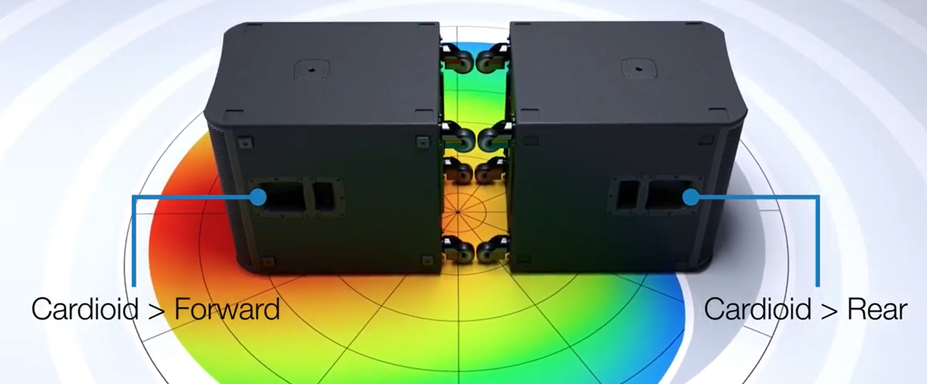
This is out of the question, the D&D 8c can be referred to as a well functioning example for radiation control via lateral slots, resulting in a cardioid pattern - see Erin's review for more details.
The design team of the forum project "Directiva r2" (design of a loudspeaker with lateral slots for cardioid radiation pattern) has made the experience that BEM simulations of speaker with slots can sufficiently describe the real loudspeaker. I start not with simulations made for the Directiva r2 speaker, but with simulations in which were certain details studied.
For those who can't do much with the terms omnidirectional and cardioid, here's a little refresher, using polar diagrams (WTF is a PD), that I also look at regularly (sorry lost the source link):
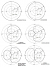
For a cardioid radiation pattern in some random frequency range, you can just saw a few holes in the side wall of a speaker (or let a woodpecker do it), but with a little more systematic approach, the results will probably be better.
The cardioid radiation pattern is influenced by the driver size, cabinet size and shape, slot position and size, number of slots and their distance from each other, the inner cabinet volume and its damping.
A little more background on cardioid speaker can be found in posts below - for example here.
2. Comparison speaker with slots to "normal" speaker - does it really matter?
There may be one or the other who thinks the whole fuss about radiation characteristics is trendy crap (I can understand that, until recently I used a 17€ flip phone...). If you belong to "one or the other" then this post might not be right for you
We are particularly interested in the upper bass to midrange frequency range of about 100 - 1000Hz. Because below 1000Hz it becomes increasingly difficult to control the radiation. Waveguides are no longer sufficient, horns become very large and specific cabinet designs can control directivity below 1kHz but below 0.5kHz it becomes very difficult.
Let's first look at the radiation of a bass-midrange driver in a "normal" closed box (CB) design. Could also be a BR speaker design, would hardly make a difference for the frequency range we are interested in.
We only take a look at the horizontal radiation pattern. The vertical radiation behavior is also influenced by lateral slots, but not to the same extent.
For those who have difficulty interpreting sonograms and for comparison with the definitions of cardioid behavior shown above, there is also a polar diagram.
In the CB-LS sketch the blue z-axis is our listening axis.
The sonogram is normalized to the axis frequency response and the black line shows the -6dB limit - which is sort of a standard measure of directivity.
The simulation was calculated only up to 4kHz.
The polar diagram shows the radiation pattern for the frequencies 100Hz, 250Hz, 500Hz and 1000Hz.
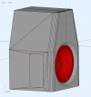
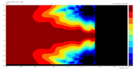
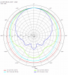
The radiation below 500Hz expands in two pronounced stages and below 200Hz is almost a omnidirectional radiation pattern. Above 500Hz the cone of the driver acts as a waveguide and controls the radiation of the bass-midrange driver - in the simulation a 10'' driver is used.
A completely "normal" behavior that should be well known to many.
However, when side slots are attached to the same cabinet, the radiation behavior changes completely.
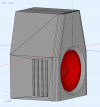
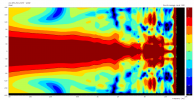
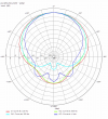
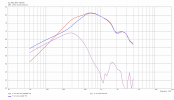
Now we have a uniform cardioid radiation pattern down to below 100Hz. The last image shows the axis frequency response of the lateral slots version (LSV) and the individual FR of woofer and the side slots.
The advantages and disadvantages are discussed in more detail in the next section.
3. Why is there increased harmonic distortion in the low frequency range?
Here in the forum it was asked a few times why the D&D 8c shows slightly increased harmonic distortion below 200Hz - more precisely slightly increased HD3*** (compared to a similar CB or BR speaker). This is a purely technical question, as in the listening sessions this did not play a role.
The (my ) theory is, that below a certain frequency the slots operate
 much like similar to an open baffle speaker and therefore SPL is cancelled by interference of front and rear emitted sound of the driver and that the "spring effect" of the air in the cabinet on the cone movement diminishes. This leads to a increased cone excursion which leads to increased third order harmonic distortion.
Whether this is the only reason for the increased HD3, I do not know.
*** This is not correct when formulated in such general terms. Why I assume that mainly HD3 will increase due to the large excursion, I try to explain here.
Further simulations seem to confirm this theory.
For this purpose we examine three cabinet versions with a 10'' bass-midrange driver:
1. cabinet 10L volume, with lateral slots (red curve below, woofer and slot SPL summed up) - LSV (lateral slots version)
2. cabinet 10L volume, closed box (cyan curve below) - CB10
3. cabinet 18L volume, closed box (green curve below) - CB18
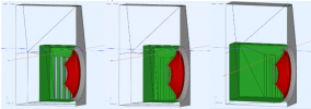
In the following picture you can see the on-axis SPL curves of all three versions. For the LSV, the SPL components of woofer (in blue) and the slots (in purple) are also drawn in the diagram.

The two SPL curves for CB10 and CB18 (cyan and green) are almost congruent. This may differ more for woofers with lower resonant frequency where the increased cabinet volume has more effect.
In the 200-600Hz frequency range, the on-axis frequency response is increased by up to 3dB compared to the CB versions, which should reduce distortion in this range compared to CB or BR versions at identical SPL. In this frequency range, the LSV is clearly superior to a "normal" CB or BR speaker, since the sound emitted from the rear of the driver increases the on-axis sound pressure level.
In the range around 170Hz the SPL of all three versions are almost identical. Below 170Hz the LSV loses significantly in SPL compared to the CB versions. At 100Hz, the SPL of the LSV is already 3dB below the CB versions. Because the phase-inverse radiated sound of the driver rear interferes with the front radiated sound and there is partial sound cancellation.
For identical SPL, the LSV would have to make significantly more cone excursion.
Now we will have a look at the excursion of the cone for all three versions (to be completely accurate, the simulation shows the excursion of the voice coil).
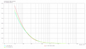
Below about 130Hz the LSV shows a larger excursion than the CB versions. The slots cause a behavior like an open baffle speaker, the "spring effect" of the air in the cabinet on the cone movement diminishes compared to the closed box. The cone movement is hardly damped by the air volume in the cabinet, since the air is shifted back and forth, like in an open baffle speaker.
These two effects (sound cancellation and less membrane damping) lead to a significantly increased cone excursion at the same SPL compared to a CB speaker concept - below 130Hz in our example.
Anyone with a better explanation for this, let me know in the comments.
UPDATE: Another possible reason is given in this post, the acoustic ports could themselves create additional harmonic distortion. In the course of the discussion, however, it is doubted that the slots themselves play a significant role in the distortion in the low frequency range.
Here you can find a simulation of the excursion behavior of the 8'' woofer of the D&D 8c and a bit further below the same simulation but as a BEM-LEM model (including simulation of hor and ver radiation behavior of the D&D 8c woofer).
3b. Does each cardioid speaker design, using slots, has increased distortion?
All details in post#51
4. What the fuss! Use an open baffle design. Duh!
One may ask how big the differences are between using a speaker with side slots and an open baffle (OB) speaker.
Are the differences so significant that the additional effort for the LSV is justified?
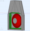
For the comparison, we redesign our sample speaker (as always woofer only) to an open baffle speaker. There are different baffle variations for OB speakers, for our comparison we choose a classic OB design and at the same time try to change as little as possible on our example speaker.
The images are in the same order, as in the examples above:
The OB speaker sketch, this time the rear view.
The sonogram is normalized to the axis frequency response and the black line shows the -6dB limit.
The simulation was calculated only up to 4kHz.
The polar diagram shows the radiation pattern for the frequencies 100Hz, 250Hz, 500Hz and 1000Hz.
The last image shows the axis frequency response of the OB speaker and the individual frequency responses of woofer front and woofer rear SPL.
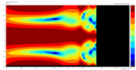
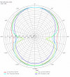
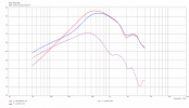
Below 700Hz, down to 100Hz, the speaker shows almost perfect dipole radiation with the usual null around 90°.
To keep the radiation of the entire OB speaker even, the tweeter must also have dipole characteristics - normal tweeters, WG or horns are not suitable for this (a second rear radiating tweeter may provide satisfactory results).
However, the difference to the cardioid radiation of a speaker with lateral slots becomes clear. The two concepts are too different for one to be considered an alternative to the other.
5. Compare the whole bunch of speaker concepts
In sections 2 and 4 we discussed and compared the horizontal radiation of closed box, lateral slots and open baffle speaker concepts.
Lateral slots can be used to extend the radiation pattern of a CB (or bass reflex) concept to lower frequencies.
The consequences for the improved radiation are that a significantly higher cone excursion is required in the low frequency range for the same SPL.
Let's take another closer look at that. The figure shows the axis frequency responses of the CB (green), LSV (blue) and OB (red) concepts.
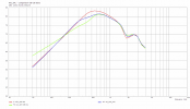
In our examples with a 10'' bass-midrange driver, significantly higher excursion must be generated for identical SPL below 170Hz with the LSV and OB concepts.
For speaker concepts with slots, the same conditions apply in the low frequency range as for open baffle concepts - you need as much displacement volume as possible to be able to cover the entire low frequency range. Or you need to adjust the crossover frequency when using the bass-midrange driver as second way in a 3-way concept.
For one or the other might be new that conversely at higher frequencies the on-axis SPL output of OB and LSV is significantly higher than that of CB (or BR) concepts.
Here LSV and OB have clear advantages over the "classic" speaker concepts.
In the frequency range 200-1500Hz OB produces the highest SPL. Because of the damping of the cabinet interior, LSV performs somewhat worse, if less damping is needed, there is room for improvement.
Index
1. Does it work?
2. Comparison speaker with slots to "normal" speaker - does it really matter?
3. Why is there increased harmonic distortion in the low frequency range?
3b. Does each cardioid speaker design, using slots, has increased distortion? - details in post#51
4. What the fuss! Use an open baffle design. Duh!
5. Compare the whole bunch of speaker concepts
1. Does it work?
This is out of the question, the D&D 8c can be referred to as a well functioning example for radiation control via lateral slots, resulting in a cardioid pattern - see Erin's review for more details.
The design team of the forum project "Directiva r2" (design of a loudspeaker with lateral slots for cardioid radiation pattern) has made the experience that BEM simulations of speaker with slots can sufficiently describe the real loudspeaker. I start not with simulations made for the Directiva r2 speaker, but with simulations in which were certain details studied.
For those who can't do much with the terms omnidirectional and cardioid, here's a little refresher, using polar diagrams (WTF is a PD), that I also look at regularly (sorry lost the source link):

For a cardioid radiation pattern in some random frequency range, you can just saw a few holes in the side wall of a speaker (or let a woodpecker do it), but with a little more systematic approach, the results will probably be better.
The cardioid radiation pattern is influenced by the driver size, cabinet size and shape, slot position and size, number of slots and their distance from each other, the inner cabinet volume and its damping.
A little more background on cardioid speaker can be found in posts below - for example here.
2. Comparison speaker with slots to "normal" speaker - does it really matter?
There may be one or the other who thinks the whole fuss about radiation characteristics is trendy crap (I can understand that, until recently I used a 17€ flip phone...). If you belong to "one or the other" then this post might not be right for you
We are particularly interested in the upper bass to midrange frequency range of about 100 - 1000Hz. Because below 1000Hz it becomes increasingly difficult to control the radiation. Waveguides are no longer sufficient, horns become very large and specific cabinet designs can control directivity below 1kHz but below 0.5kHz it becomes very difficult.
Let's first look at the radiation of a bass-midrange driver in a "normal" closed box (CB) design. Could also be a BR speaker design, would hardly make a difference for the frequency range we are interested in.
We only take a look at the horizontal radiation pattern. The vertical radiation behavior is also influenced by lateral slots, but not to the same extent.
For those who have difficulty interpreting sonograms and for comparison with the definitions of cardioid behavior shown above, there is also a polar diagram.
In the CB-LS sketch the blue z-axis is our listening axis.
The sonogram is normalized to the axis frequency response and the black line shows the -6dB limit - which is sort of a standard measure of directivity.
The simulation was calculated only up to 4kHz.
The polar diagram shows the radiation pattern for the frequencies 100Hz, 250Hz, 500Hz and 1000Hz.


The radiation below 500Hz expands in two pronounced stages and below 200Hz is almost a omnidirectional radiation pattern. Above 500Hz the cone of the driver acts as a waveguide and controls the radiation of the bass-midrange driver - in the simulation a 10'' driver is used.
A completely "normal" behavior that should be well known to many.
However, when side slots are attached to the same cabinet, the radiation behavior changes completely.


Now we have a uniform cardioid radiation pattern down to below 100Hz. The last image shows the axis frequency response of the lateral slots version (LSV) and the individual FR of woofer and the side slots.
The advantages and disadvantages are discussed in more detail in the next section.
3. Why is there increased harmonic distortion in the low frequency range?
Here in the forum it was asked a few times why the D&D 8c shows slightly increased harmonic distortion below 200Hz - more precisely slightly increased HD3*** (compared to a similar CB or BR speaker). This is a purely technical question, as in the listening sessions this did not play a role.
The (my
Whether this is the only reason for the increased HD3, I do not know.
*** This is not correct when formulated in such general terms. Why I assume that mainly HD3 will increase due to the large excursion, I try to explain here.
Further simulations seem to confirm this theory.
For this purpose we examine three cabinet versions with a 10'' bass-midrange driver:
1. cabinet 10L volume, with lateral slots (red curve below, woofer and slot SPL summed up) - LSV (lateral slots version)
2. cabinet 10L volume, closed box (cyan curve below) - CB10
3. cabinet 18L volume, closed box (green curve below) - CB18

In the following picture you can see the on-axis SPL curves of all three versions. For the LSV, the SPL components of woofer (in blue) and the slots (in purple) are also drawn in the diagram.
The two SPL curves for CB10 and CB18 (cyan and green) are almost congruent. This may differ more for woofers with lower resonant frequency where the increased cabinet volume has more effect.
In the 200-600Hz frequency range, the on-axis frequency response is increased by up to 3dB compared to the CB versions, which should reduce distortion in this range compared to CB or BR versions at identical SPL. In this frequency range, the LSV is clearly superior to a "normal" CB or BR speaker, since the sound emitted from the rear of the driver increases the on-axis sound pressure level.
In the range around 170Hz the SPL of all three versions are almost identical. Below 170Hz the LSV loses significantly in SPL compared to the CB versions. At 100Hz, the SPL of the LSV is already 3dB below the CB versions. Because the phase-inverse radiated sound of the driver rear interferes with the front radiated sound and there is partial sound cancellation.
For identical SPL, the LSV would have to make significantly more cone excursion.
Now we will have a look at the excursion of the cone for all three versions (to be completely accurate, the simulation shows the excursion of the voice coil).

Below about 130Hz the LSV shows a larger excursion than the CB versions. The slots cause a behavior like an open baffle speaker, the "spring effect" of the air in the cabinet on the cone movement diminishes compared to the closed box. The cone movement is hardly damped by the air volume in the cabinet, since the air is shifted back and forth, like in an open baffle speaker.
These two effects (sound cancellation and less membrane damping) lead to a significantly increased cone excursion at the same SPL compared to a CB speaker concept - below 130Hz in our example.
Anyone with a better explanation for this, let me know in the comments.
UPDATE: Another possible reason is given in this post, the acoustic ports could themselves create additional harmonic distortion. In the course of the discussion, however, it is doubted that the slots themselves play a significant role in the distortion in the low frequency range.
Here you can find a simulation of the excursion behavior of the 8'' woofer of the D&D 8c and a bit further below the same simulation but as a BEM-LEM model (including simulation of hor and ver radiation behavior of the D&D 8c woofer).
3b. Does each cardioid speaker design, using slots, has increased distortion?
All details in post#51
4. What the fuss! Use an open baffle design. Duh!
One may ask how big the differences are between using a speaker with side slots and an open baffle (OB) speaker.
Are the differences so significant that the additional effort for the LSV is justified?
For the comparison, we redesign our sample speaker (as always woofer only) to an open baffle speaker. There are different baffle variations for OB speakers, for our comparison we choose a classic OB design and at the same time try to change as little as possible on our example speaker.
The images are in the same order, as in the examples above:
The OB speaker sketch, this time the rear view.
The sonogram is normalized to the axis frequency response and the black line shows the -6dB limit.
The simulation was calculated only up to 4kHz.
The polar diagram shows the radiation pattern for the frequencies 100Hz, 250Hz, 500Hz and 1000Hz.
The last image shows the axis frequency response of the OB speaker and the individual frequency responses of woofer front and woofer rear SPL.


Below 700Hz, down to 100Hz, the speaker shows almost perfect dipole radiation with the usual null around 90°.
To keep the radiation of the entire OB speaker even, the tweeter must also have dipole characteristics - normal tweeters, WG or horns are not suitable for this (a second rear radiating tweeter may provide satisfactory results).
However, the difference to the cardioid radiation of a speaker with lateral slots becomes clear. The two concepts are too different for one to be considered an alternative to the other.
5. Compare the whole bunch of speaker concepts
In sections 2 and 4 we discussed and compared the horizontal radiation of closed box, lateral slots and open baffle speaker concepts.
Lateral slots can be used to extend the radiation pattern of a CB (or bass reflex) concept to lower frequencies.
The consequences for the improved radiation are that a significantly higher cone excursion is required in the low frequency range for the same SPL.
Let's take another closer look at that. The figure shows the axis frequency responses of the CB (green), LSV (blue) and OB (red) concepts.

In our examples with a 10'' bass-midrange driver, significantly higher excursion must be generated for identical SPL below 170Hz with the LSV and OB concepts.
For speaker concepts with slots, the same conditions apply in the low frequency range as for open baffle concepts - you need as much displacement volume as possible to be able to cover the entire low frequency range. Or you need to adjust the crossover frequency when using the bass-midrange driver as second way in a 3-way concept.
For one or the other might be new that conversely at higher frequencies the on-axis SPL output of OB and LSV is significantly higher than that of CB (or BR) concepts.
Here LSV and OB have clear advantages over the "classic" speaker concepts.
In the frequency range 200-1500Hz OB produces the highest SPL. Because of the damping of the cabinet interior, LSV performs somewhat worse, if less damping is needed, there is room for improvement.
Last edited:

