MAB
Major Contributor
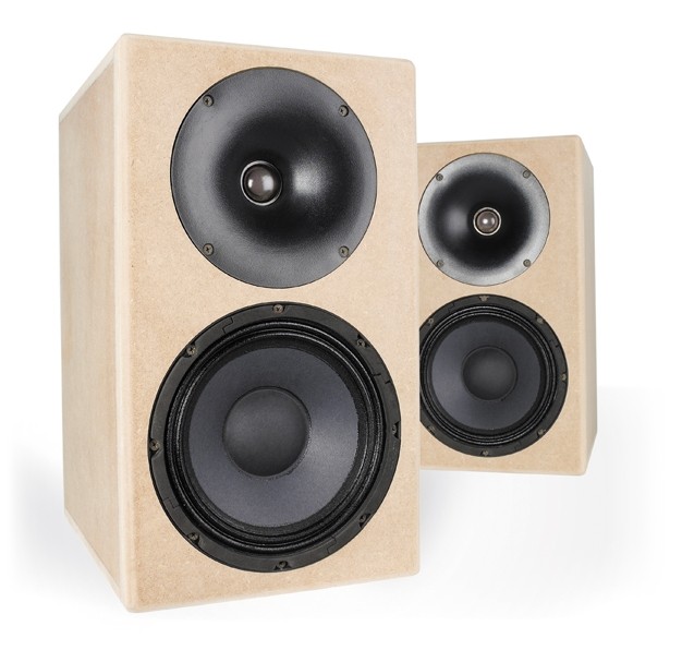
FFLOTSAM (Fabricated From LeftOver Things Studio Active Monitor)
Active DSP speakers, for testing a few ideas
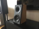
I had some stuff lying around; a few random Baltic Birch-ply panels, some countertop material, a few cans of partially used brown spray paint, and some not-too clumpy spar varnish (that caused more effort than savings…) I also had the driver elements from my old disassembled Seas Thor speakers. The Thors had evolved over nearly 20 years from the original DIY design through the full range of cabinet and crossover modifications that many Thor builders pursued. I later converted them to analog active using Linkwitz crossover boards including integrated subwoofers. Thor eventually ended up active-DSP with a MiniDSP 4x10HD, which worked great. I really enjoyed the flexibility of active, even more so active with DSP. I scrapped the Thors last year since they had been eclipsed by a pair of Genelec Ones. While they sounded great, they were gigantic with an umbilical running to a rack of amps, always a bit too much of a science project…
Science has struck again now that I joined ASR. And I thought I would build a pair of mini monitors to test out a few ideas. One involves dealing with resonance peaks in midbass drivers. The Seas W18E001 woofer from the Thors is ideal for this since it has an epic breakup mode at 4.3kHz. I also wanted to go through a basic active speaker build since there have been recent discussions here about how easy and superior DSP is. Lastly, I figured that it would be fun and I wanted an alternative to a pair of Rauna Freja that are my primary computer speakers.
Table of contents:
Build and initial testing of the W18E001 woofer
Reduction in 3rd order distortion observation
Part 2 of testing the woofer's resonance
DSP vs. Passive/Active Hybrid
Full speaker testing with both passive and DSP notch
The drivers:

The tweeter is the T25CF-002. It’s a soft-dome tweeter made out of synthetic fabric. It can be crossed over pretty low for a tweeter (500Hz resonance frequency), but I did overheat a pair experimenting with a low crossover point a few years ago. So despite the capability to play low, there is only so much thermal power that can be dissipated from the motor.
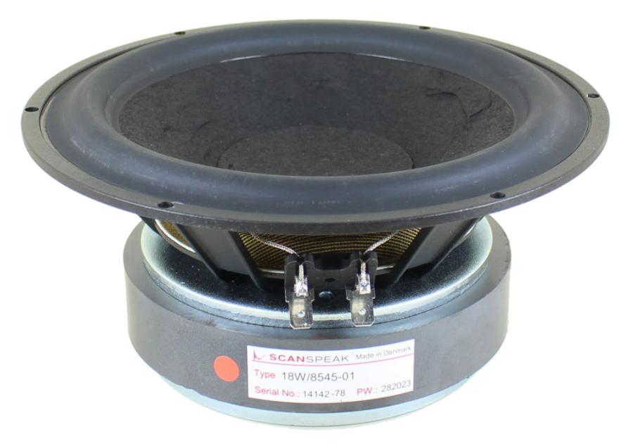
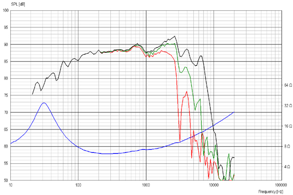
The woofer is the W18E001. It has a magnesium cone. I have both the first and second versions of this driver. Here are the published and measured frequency responses of the first version:

There is a lot going on centered at 4.3kHz. There is a breakup mode where the cone starts looking more like a potato chip with a 9dB fundamental peak, but there are other things going on as well, like a null at 3kHz. These have harmonics that can be seen at high frequencies. The measurement and the data from Seas are in agreement. Like driving a car on a washboard road, you will either need to avoid driving the cone near these resonances or additional damping needs to be added to mechanically control the resonance (like a shock-absorber!!!). You could use a low tweeter crossover and risk melting tweeters (like me) or build a three-way with a proper midrange. Or you could use a DSP notch to reduce the signal at resonance. You could also use a passive notch filter.
Construction:
I built the drivers into 11 liter sealed boxes with an 20cm wide front baffle.

The front panel is 38mm thick cheap countertop. I rounded the front edges, chamfered the cutouts, etc. I recently adjusted the saw and things came out pretty true.

I use PVA wood glue for the cabinet joints, but I like the polyurethane glue for braces since it expands, especially if you lightly wet the wood surface before gluing. The braces are kiln-dried Douglass Fir which should add warmth to the midrange . I’m not sure how long the front face of the cabinet is going to last since it will expand and contract much differently than the plywood cabinet.

The Epifanes varnish I had was old and a bit clotted, I eventually made it work but it is the least appealing part of the cabinets. Even the mismatched brown spray paint turned out better. There is a reason that artisans put on 12-coat finishes, the first 11 didn’t work out and had to be sanded off! The cabinets came together well and the faces press-fit nicely. They might look at home on top of some cinder-block bookshelves, perfect for the man-cave but not quite fine furniture.
Setup:
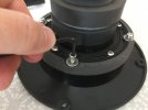
The speakers went together easily. I stuffed them with jute and poly-fill. The cabinets are nice and dead. I don’t have stands built yet, but I was able to put the speakers in my basement office, plug them in, implement simple Rev0 DSP crossover at 2.4kHz and start playing music within an hour of final assembly. I even got the levels pretty much right.

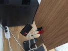
I forgot to mention the sea of electronics. And the wire. Lots of cable-lifters needed too I guess!!! I also forgot to mention that FFLOTSAM will include subwoofers, called JETSAM of course, using Seas W26FX001 aluminum/magnesium alloy woofers in 28 liter boxes.
 I have four but will likely only use two! The Marantz monoblock amps drive the FFLOTSAM, the Bryston powers the JETSAM subs. A MiniDSP Flex Eight does the rest very nicely.

Right off the bat I notice a metallic leanness to the sound, presumably due to the woofer’s breakup mode (even with 24dB/octave crossover at 2.4kHz) and the lack of baffle compensation. Moving the crossover point to an unreasonably low 1.4kHz subjectively improved the shrieking, moving the crossover to 3kHz made it sound worse. This kind-of confirms the woofer breakup needs dealing with at any reasonable crossover frequency. All in all, with the first-pass levels and filters it sounded pretty OK and played so loud I had a hard time fighting my way back to the desk to grab the remote. Engaging the subwoofers addressed (or covered) some of the leanness, but something needs to be done about the woofers.
Measurements:
Going back to the W18E001 v1 frequency response, I applied EQ to reduce the signal at the 4.3kHz peak. A -9dB notch with Q=4 seemed best. Adding a notch at 3kHz for the null and a shelf for the baffle and we end up with pretty flat response I think. You can really hear the resonance at 4.3kHz during the sweeps when no notch is present, I am pretty sure the dip at 3kHz makes it sound even worse.

Re-implementing the Rev0 crossover slopes and levels with these DSP filters the speakers sound surprisingly good to me without further fiddling. Any additional Bass EQ would be perilous at anything but moderate volume so subwoofers are needed, at least to suit my taste. There are nits to pick, but I think I could live with this. And, it was easy for me to get up and running quickly and easily, and implement EQ based on measurements. Granted, I have experience with these drivers from the DIY Thor saga, but no way I could have had the system up and running and sounding like this with passive crossovers so soon. I felt the same when I went from passive crossovers on the Thors to analog active; implementing changes was just so much easier . Even more so with DSP
 . The penalty with active is that sea of electronics and wires.
But before I build this out to the greatest sounding speakers in the world, my goal is to evaluate notches first. And I wanted to do a comparison of active vs. passive notch approaches. Also, I was made aware by @thewas of a PuriFi whitepaper on resonant breakup modes which indicated a parallel notch filter (implemented in series with the driver) potentially outperforms an active notch.
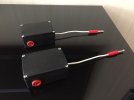
So, I made a fixture to allow easy swaps of components for a passive notch filter.

Below is the response of the W18E001 v1 driver with and without notch. DSP notch is at 4.3 kHz, Q=4, and Gain = -9dB. The passive notch was achieved with C=8.2uF, L=0.15mH, and R=100Ω. 12.5Ω, 25Ω, and 50Ω were tried as well. I think somewhere between 50Ω and 100Ω is where the attenuation needs to be. I tried moving the L and C around too, these values worked the best but I admit I was limited slightly to parts on hand. Suffice to say, both passive and active notch filters do a good job of taming the peak. Interesting observation, there is less oscillation in the higher order harmonics (8.6kHz) with the passive notch than the DSP notch. Perhaps because my DSP and passive filter shapes are not absolutely the same. Also, I did feel that there may be more than one thing going on at 4.3kHz which may require more than one notch. But both filter approaches work well I think. Sweeps sound smooth with either, with no more ear-ringing howl.

Looking at the range of notch filters, 12.5Ω provides insufficient attenuation. 50Ω and 100Ω look best, the truth may be in between. Note the distortion; 100Ω appears to be best, 50Ω close second, 12.5Ω third for the passive notch. The DSP EQ (-9dB, Q=4, f=4300) does not appear to perform as well as the 50Ω and 100Ω passive notch for distortion.

I can’t honestly hear the differences between the 50Ω and 100Ω passives and the DSP notches. Sweeps sound great with all three. Adding the 3kHz notch, the shelf, and the crossover filters back in, I swapped the passive for active notch a few times. Both sound good listening to music.
Putting it all together, I added the 3kHz notch and the 500Hz step for the baffle and ran sweeps with no notch, the passive notch with R=100Ω, and the DSP notch. Both notches provide useable response and sounded smooth on the sweeps. I still wonder if I have the right DSP notch when I look at the distortion graph

Another question, what is going on at 1.5kHz on the distortion plot??? The Basic DSP only and Basic DSP plus active notch have a spike in distortion, while the Basic DSP plus passive has a much lower spike? I can’t imagine why the passive notch is reducing distortion at 1.5kHz too..
All those details aside, I got the speakers back on my desktop with the crossovers in place and they sound good. I am going to swap back and forth between the active and passive notches and see if I can hear a difference.
Regarding notches, I feel that the passive notch is less flexible and convenient but does outperform the active here. Whether it is audible, I am not sure, especially if you cross the driver over low. I reject the notion that a passive element somehow reduces the dynamics, or creates some high frequency grain, or prevents your amp from controlling the driver, or blurs the image, etc. In fact, I think it is incrementally better in the case where you have a large cone breakup mode. And, if you quickly check out the Seas Excel woofer line, you will see they have lots of drivers with large breakup modes (not just the metal ones, graphene, and treated-paper as well and they will all have a metallic ring... ) High-end drivers with large resonances aren't even unique to Seas.
Regarding ease... In a way, DSP reduces building speakers to building good cabinets. There were threads a few months ago wondering why everybody didn't just convert their passive speakers to active. And threads that passives sound worse than actives, we seemed to damn every capacitor and inductor to the hell of lo-fi in that one. Another that in the future no more capacitors will exist, or all the electricity shunted to ground through everybody's passive crossovers was enough to power all of the clothes driers in the world... OK, those two I made up. But seriously, there are just too many great sounding passive speakers (and perhaps too many bad sounding actives) for these to be reasonable. Not to say that active DSP speakers are not the bright future, but the picture is a bit more nuanced than some of the discussions. Hope this helps.
I will test out the v2 of the the W18 woofer next. It has a larger peak, at higher frequency than v1.
Edit (Oct 28): replaced graph of W18 spec sheet actual vs. published frequency response with a graph that has correctly aligned frequency axes. Added linked table of contents.
Active DSP speakers, for testing a few ideas
I had some stuff lying around; a few random Baltic Birch-ply panels, some countertop material, a few cans of partially used brown spray paint, and some not-too clumpy spar varnish (that caused more effort than savings…) I also had the driver elements from my old disassembled Seas Thor speakers. The Thors had evolved over nearly 20 years from the original DIY design through the full range of cabinet and crossover modifications that many Thor builders pursued. I later converted them to analog active using Linkwitz crossover boards including integrated subwoofers. Thor eventually ended up active-DSP with a MiniDSP 4x10HD, which worked great. I really enjoyed the flexibility of active, even more so active with DSP. I scrapped the Thors last year since they had been eclipsed by a pair of Genelec Ones. While they sounded great, they were gigantic with an umbilical running to a rack of amps, always a bit too much of a science project…
Science has struck again now that I joined ASR. And I thought I would build a pair of mini monitors to test out a few ideas. One involves dealing with resonance peaks in midbass drivers. The Seas W18E001 woofer from the Thors is ideal for this since it has an epic breakup mode at 4.3kHz. I also wanted to go through a basic active speaker build since there have been recent discussions here about how easy and superior DSP is. Lastly, I figured that it would be fun and I wanted an alternative to a pair of Rauna Freja that are my primary computer speakers.
Table of contents:
Build and initial testing of the W18E001 woofer
Reduction in 3rd order distortion observation
Part 2 of testing the woofer's resonance
DSP vs. Passive/Active Hybrid
Full speaker testing with both passive and DSP notch
The drivers:
The tweeter is the T25CF-002. It’s a soft-dome tweeter made out of synthetic fabric. It can be crossed over pretty low for a tweeter (500Hz resonance frequency), but I did overheat a pair experimenting with a low crossover point a few years ago. So despite the capability to play low, there is only so much thermal power that can be dissipated from the motor.
The woofer is the W18E001. It has a magnesium cone. I have both the first and second versions of this driver. Here are the published and measured frequency responses of the first version:
There is a lot going on centered at 4.3kHz. There is a breakup mode where the cone starts looking more like a potato chip with a 9dB fundamental peak, but there are other things going on as well, like a null at 3kHz. These have harmonics that can be seen at high frequencies. The measurement and the data from Seas are in agreement. Like driving a car on a washboard road, you will either need to avoid driving the cone near these resonances or additional damping needs to be added to mechanically control the resonance (like a shock-absorber!!!). You could use a low tweeter crossover and risk melting tweeters (like me) or build a three-way with a proper midrange. Or you could use a DSP notch to reduce the signal at resonance. You could also use a passive notch filter.
Construction:
I built the drivers into 11 liter sealed boxes with an 20cm wide front baffle.
The front panel is 38mm thick cheap countertop. I rounded the front edges, chamfered the cutouts, etc. I recently adjusted the saw and things came out pretty true.
I use PVA wood glue for the cabinet joints, but I like the polyurethane glue for braces since it expands, especially if you lightly wet the wood surface before gluing. The braces are kiln-dried Douglass Fir which should add warmth to the midrange
The Epifanes varnish I had was old and a bit clotted, I eventually made it work but it is the least appealing part of the cabinets. Even the mismatched brown spray paint turned out better. There is a reason that artisans put on 12-coat finishes, the first 11 didn’t work out and had to be sanded off!
Setup:
The speakers went together easily. I stuffed them with jute and poly-fill. The cabinets are nice and dead. I don’t have stands built yet, but I was able to put the speakers in my basement office, plug them in, implement simple Rev0 DSP crossover at 2.4kHz and start playing music within an hour of final assembly. I even got the levels pretty much right.
I forgot to mention the sea of electronics. And the wire. Lots of cable-lifters needed too I guess!!!
Right off the bat I notice a metallic leanness to the sound, presumably due to the woofer’s breakup mode (even with 24dB/octave crossover at 2.4kHz) and the lack of baffle compensation. Moving the crossover point to an unreasonably low 1.4kHz subjectively improved the shrieking, moving the crossover to 3kHz made it sound worse. This kind-of confirms the woofer breakup needs dealing with at any reasonable crossover frequency. All in all, with the first-pass levels and filters it sounded pretty OK and played so loud I had a hard time fighting my way back to the desk to grab the remote. Engaging the subwoofers addressed (or covered) some of the leanness, but something needs to be done about the woofers.
Measurements:
Going back to the W18E001 v1 frequency response, I applied EQ to reduce the signal at the 4.3kHz peak. A -9dB notch with Q=4 seemed best. Adding a notch at 3kHz for the null and a shelf for the baffle and we end up with pretty flat response I think. You can really hear the resonance at 4.3kHz during the sweeps when no notch is present, I am pretty sure the dip at 3kHz makes it sound even worse.
Re-implementing the Rev0 crossover slopes and levels with these DSP filters the speakers sound surprisingly good to me without further fiddling. Any additional Bass EQ would be perilous at anything but moderate volume so subwoofers are needed, at least to suit my taste. There are nits to pick, but I think I could live with this. And, it was easy for me to get up and running quickly and easily, and implement EQ based on measurements. Granted, I have experience with these drivers from the DIY Thor saga, but no way I could have had the system up and running and sounding like this with passive crossovers so soon. I felt the same when I went from passive crossovers on the Thors to analog active; implementing changes was just so much easier
But before I build this out to the greatest sounding speakers in the world, my goal is to evaluate notches first.
So, I made a fixture to allow easy swaps of components for a passive notch filter.
Below is the response of the W18E001 v1 driver with and without notch. DSP notch is at 4.3 kHz, Q=4, and Gain = -9dB. The passive notch was achieved with C=8.2uF, L=0.15mH, and R=100Ω. 12.5Ω, 25Ω, and 50Ω were tried as well. I think somewhere between 50Ω and 100Ω is where the attenuation needs to be. I tried moving the L and C around too, these values worked the best but I admit I was limited slightly to parts on hand. Suffice to say, both passive and active notch filters do a good job of taming the peak. Interesting observation, there is less oscillation in the higher order harmonics (8.6kHz) with the passive notch than the DSP notch. Perhaps because my DSP and passive filter shapes are not absolutely the same. Also, I did feel that there may be more than one thing going on at 4.3kHz which may require more than one notch. But both filter approaches work well I think. Sweeps sound smooth with either, with no more ear-ringing howl.
Looking at the range of notch filters, 12.5Ω provides insufficient attenuation. 50Ω and 100Ω look best, the truth may be in between. Note the distortion; 100Ω appears to be best, 50Ω close second, 12.5Ω third for the passive notch. The DSP EQ (-9dB, Q=4, f=4300) does not appear to perform as well as the 50Ω and 100Ω passive notch for distortion.
I can’t honestly hear the differences between the 50Ω and 100Ω passives and the DSP notches. Sweeps sound great with all three. Adding the 3kHz notch, the shelf, and the crossover filters back in, I swapped the passive for active notch a few times. Both sound good listening to music.
Putting it all together, I added the 3kHz notch and the 500Hz step for the baffle and ran sweeps with no notch, the passive notch with R=100Ω, and the DSP notch. Both notches provide useable response and sounded smooth on the sweeps. I still wonder if I have the right DSP notch when I look at the distortion graph
Another question, what is going on at 1.5kHz on the distortion plot??? The Basic DSP only and Basic DSP plus active notch have a spike in distortion, while the Basic DSP plus passive has a much lower spike? I can’t imagine why the passive notch is reducing distortion at 1.5kHz too..
All those details aside, I got the speakers back on my desktop with the crossovers in place and they sound good. I am going to swap back and forth between the active and passive notches and see if I can hear a difference.
Regarding notches, I feel that the passive notch is less flexible and convenient but does outperform the active here. Whether it is audible, I am not sure, especially if you cross the driver over low. I reject the notion that a passive element somehow reduces the dynamics, or creates some high frequency grain, or prevents your amp from controlling the driver, or blurs the image, etc. In fact, I think it is incrementally better in the case where you have a large cone breakup mode. And, if you quickly check out the Seas Excel woofer line, you will see they have lots of drivers with large breakup modes (not just the metal ones, graphene, and treated-paper as well and they will all have a metallic ring...
Regarding ease... In a way, DSP reduces building speakers to building good cabinets. There were threads a few months ago wondering why everybody didn't just convert their passive speakers to active. And threads that passives sound worse than actives, we seemed to damn every capacitor and inductor to the hell of lo-fi in that one. Another that in the future no more capacitors will exist, or all the electricity shunted to ground through everybody's passive crossovers was enough to power all of the clothes driers in the world... OK, those two I made up.
I will test out the v2 of the the W18 woofer next. It has a larger peak, at higher frequency than v1.
Edit (Oct 28): replaced graph of W18 spec sheet actual vs. published frequency response with a graph that has correctly aligned frequency axes. Added linked table of contents.
Last edited:

