• WANTED: Happy members who like to discuss audio and other topics related to our interest. Desire to learn and share knowledge of science required. There are many reviews of audio hardware and expert members to help answer your questions. Click here to have your audio equipment measured for free!

Topping PA5 Review (Amplifier)

pma

Major Contributor
Joined
Feb 23, 2019
Messages
4,612
Likes
10,789
Location
Prague
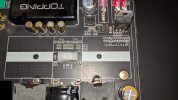
Normally, one would place an kind of volume pot after the input diff-amp (the "dereferencer") so that it never compromises CMRR.

I think we know this, however then 4 gang pot is not used. If there is a 4 gang pot it indicates to 2 independent signal paths for + and - branches through the whole amp or that the pot is before the input stage. Anyway the use of 4 gang pot compromises the CMRR.
 

Dynky

New Member
Joined
Aug 1, 2021
Messages
1
Likes
0
Can someone please check and confirm whether a pair of Neutrik NA3FP adapters will fit on the inputs?
 

KSTR

Major Contributor
Joined
Sep 6, 2018
Messages
2,792
Likes
6,252
Location
Berlin, Germany
I think we know this, however then 4 gang pot is not used. If there is a 4 gang pot it indicates to 2 independent signal paths for + and - branches through the whole amp or that the pot is before the input stage. Anyway the use of 4 gang pot compromises the CMRR.
You got me wrong it seems. What I mean is the typical re-balancer circuit at the input which has balanced output signal with CM=0 (and some DM gain, perhaps), and after that you need a 2-gang pot per channel to control volume for the output paths in most any pot configuration, be it simple voltage divider + buffer/gain cell (with log pot) or inverting feedback divider of the output amp itself (linear).
 

nhs

Active Member
Joined
Apr 16, 2021
Messages
145
Likes
78
I think we know this, however then 4 gang pot is not used. If there is a 4 gang pot it indicates to 2 independent signal paths for + and - branches through the whole amp or that the pot is before the input stage. Anyway the use of 4 gang pot compromises the CMRR.
As your previous post, I am also very interested in a measurement at another position of the volume knob, at about 9db gain would be fine. I personally have to attenuate the gain to match the level of other surround amp's. Hope, @amirm would do it.
 

Papaya_X

Member
Joined
Nov 26, 2021
Messages
42
Likes
15
Why do these things? Which measurement do you hope to improve? It already measures spectacularly.
I hope to give more power output ?? I don't know that's why I am asking what would be the improvement if there is any
 

Calleberg

Active Member
Joined
Aug 23, 2021
Messages
102
Likes
136
Location
Sweden
I hope to give more power output ?? I don't know that's why I am asking what would be the improvement if there is any

Well to start, the standard PSU is 38V, which is also the maximum rating of the TPA3251, if thats whats inside... So a 36V PSU is not going to help things.

You will have to wait until they release the 260Wx2@4Ohm TPA3255 Version with 52V 16A PSU :)
 

Papaya_X

Member
Joined
Nov 26, 2021
Messages
42
Likes
15
Well to start, the standard PSU is 38V, which is also the maximum rating of the TPA3251, if thats whats inside... So a 36V PSU is not going to help things
Yes it was a mistake, would there be any benefits in terms of power (not measurements) to run a 38V 6A/8A PSU with this amp ?
 

TNT

Active Member
Joined
Jun 24, 2020
Messages
244
Likes
157
Why do these things? Which measurement do you hope to improve? It already measures spectacularly.
Maybe it will improve its impulse/dynamic behaviour thanks to a battery based PSU low impedance and current capability. All the measurements was steady state so this aspects isn't covered as I see it. To make a car analogy which we all love som much; ASR is testing highway crusing comfort but no acceleration or off-road tests are performed ;)

//
 
Last edited:

Toku

Major Contributor
Joined
Apr 4, 2018
Messages
2,435
Likes
2,839
Location
Japan
I examined the pin arrangement based on the close-up photograph of this IC chip. As a result, I was convinced that it was TPA3251 or TPA3255. Furthermore, considering that the power supply voltage of PA5 is 38V, it can be said that it is TPA3255. Probably no doubt.
 

Attachments

  • ToppingPA5_26.PNG
    ToppingPA5_26.PNG
    2 MB · Views: 319

F1308

Major Contributor
Joined
May 24, 2020
Messages
1,060
Likes
918
Topping PA5 appears as P50...
 

Attachments

  • PA5 shown as P50.jpg
    PA5 shown as P50.jpg
    140.1 KB · Views: 176

Toku

Major Contributor
Joined
Apr 4, 2018
Messages
2,435
Likes
2,839
Location
Japan
All the true hole solder joints and the hand Solder inductors look bad and inconsistent.
And i hate that they did not clean up the flux
When I look at the posted photos, I get a lot of doubts.

1. As a product version, the PC board is dirty. There are many scratches on the parts used. Isn't this PA5 a prototype for testing?
2. The information printed on the board is blacked out to hide it. I don't think this kind of treatment is necessary for the product version. Maybe it was a photo taken before the product was announced?
 

pma

Major Contributor
Joined
Feb 23, 2019
Messages
4,612
Likes
10,789
Location
Prague
1. As a product version, the PC board is dirty. There are many scratches on the parts used. Isn't this PA5 a prototype for testing?

To me, it looks like just a functional sample. If it was a serial production piece, then the factory quality standards would be very, very low.
 

nhs

Active Member
Joined
Apr 16, 2021
Messages
145
Likes
78
To me, it looks like just a functional sample. If it was a serial production piece, then the factory quality standards would be very, very low.
Afaik, the pics are taken from the device of @genfreeciv. It must be also a piece from the serial production.
 

Matias

Master Contributor
Forum Donor
Joined
Jan 1, 2019
Messages
5,089
Likes
10,949
Location
São Paulo, Brazil
A little dusty from the factory but no big deal. I also do product photography, and close up pictures tend to magnify the dust.
 

genfreeciv

Member
Joined
Sep 29, 2021
Messages
20
Likes
83
Hi all,
The product that I took teardown photos was delivered through amazon.co.jp.
I used a flash when I took those photos to clearly record the text printed on the circuit elements , so I think the dust and scraches stood out.
It's true that it's not as clean as the inside of the MOTU M2 I once opened, but I think it's cleaner than that of a BA100 of Breeze audio from China.
 

Lambda

Major Contributor
Joined
Mar 22, 2020
Messages
1,792
Likes
1,530
Also it is kind of stupid to put a heat sink like this in a case like this.
Airflow trough fines is sub optimal to say the least.
a proper Thermal interface to the cases would be a better solution for sure but i guess also a more expensive and complicated solution

genfreeciv

Wat kind of Processing HDR, tone mapping, Clarity, local contrast, dynamic range compression. or how ever the manufacture calling it are you using?

Maybe back of on this slider... like a lot :p
 
  • Like
Reactions: pma

pma

Major Contributor
Joined
Feb 23, 2019
Messages
4,612
Likes
10,789
Location
Prague
Also it is kind of stupid to put a heat sink like this in a case like this.
Airflow trough fines is sub optimal to say the least.
a proper Thermal interface to the cases would be a better solution for sure but i guess also a more expensive and complicated solution
It is the same issue as with AIYIMA A07 that I bought for testing and posted a lot of results. But this one is too expensive to me to buy it just from a simple curiosity reason. I am afraid that no one else here would be willing to perform a continuous power test.
 
Top Bottom