restorer-john
Grand Contributor
Although, the new 50 GHz TDR we got at work would probably show all sorts of wiggles into a speaker cable.
Take it home Don and have some fun. We'd all like to see your investigations.
")

Although, the new 50 GHz TDR we got at work would probably show all sorts of wiggles into a speaker cable.
Just another reason to go active folks... no 'debatable' speaker cable lengths messing up fidelity.
Indeed. I can't imagine people or companies dishonest enough to claim cables would make differences in such setups.
And, if they ever did, I do not doubt that golden-ears reviewers would immediately expose the scam. I can't wait
Take it home Don and have some fun. We'd all like to see your investigations.
@amirm As I don't have the Isolda cable I can't do any comparisons so I have this 'theory' that would be easy to put to the test.
Assuming the high capacitance (and low inductance) is the reason for the improvements (regardless of theory) and other manufacturers exist that have high capacitance cables it occurred to me that maybe the rather high capacitance effect alone could be easily tested.
I would like to see the following test:
Generic (low resistance) cable with similar length as the Isolda with on the cable input 1x 3.3uH inductor (should be air wound and plenty of wire thickness to protect your amps) on the hot end of the cable and on the output of the cable a capacitor with about the same value as the measured capacitance of the isolda - measured (or estimated) capacitance of the generic cable.
After all the Isolda cable is just a very long stretched capacitor in essence that connects the amp to the speaker.
Just another reason to go active folks... no 'debatable' speaker cable lengths messing up fidelity.
The theory behind this test is to see whether that high capacitance is the reason or the waveguide theory is valid after all despite the theory saying the wavelengths are too short for this.
I can't see DC being improved by a wave guide nor say 100Hz for that matter.
But what I can 'imagine' is that when using a bandwidth limited 10kHz squarewave (which the output of any amplifier is) still has a lot of ultrasonics with a lot of energy well up to 100kHz for instance. We are clearly 'looking' above 50kHz here so the amp used should at least reach this.
At the end of the cable such a signal will be greeted by a capacitance of say 27nF or so (10m cable) which will have an impedance of around 50Ohm which is lower than the 'about 200 Ohm'. When this is in parallel with a speaker it will be lower.
Even better .. use the same Zobel as Towshend uses (10 Ohm + 0.22uF which is about 16 Ohm around 100kHz) and it becomes around 8 Ohm there.
No reason to 'reflect' anything there any more.
The extra capacitance will effectively short higher harmonics of say 1MHz or higher when present.
Another experiment could be to not even use the 3.3uH inductor and extra capacitor but only used the Zobel at the end of the cable ?
I assume mr. Townshend already has done these experiments and got better results with his (quite different geometry) cable.
In that case geometry is what matters.
When the same effect is achieved with just the Zobel network or the extra inductor + capacitor + Zobel then every handy DIY-er or handy business man can make 2 'cable interface boxes' and make any cable 'directional'.
I find the results Townshend got 'intriguing' enough to be tested by a third party and made more public.
When indeed Townshend's theory is true (reflections and geometry) then there is reasonable doubt that this matters in speaker cables.
Thanks for your reply.
The fact that a specific amplifier remains stable under simulations does not mean all amplifiers connected to certain speakers remain stable.
Also the 8 Ohm argument is nonsense as no speaker cable reaches anywhere near 8 Ohm at audio frequencies. Also there are no speakers that have an 8Ohm impedance >100kHz they may well be hundreds of Ohms or even lower.
Also amplifiers have a close to 0 Ohm output R and have to deliver current into complex (inductive/capacitive) loads and not in a nice resistive 8 Ohm load. So there is no impedance matching at all as the output R of the amp is not 8 Ohm.
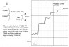
Can you zoom in on those squarewave peaks to actually show they are reflections.
It is quite easy to see if they really 'distort' the signal by doing measurements and/or nulls at the begin and end of the cable (connected to a real load)
The second video seems to show resistive differences (given the low frequencies) and cannot possibly come from reflections. The wavelenghts simply are too long for audio frequencies.
Man, that cable theory "white paper" is just begging for an annotated version.
For those of us who use cables for audio rather than shortwave transmitters, regular wire works just fine.
This article was written in 1998.From the same paper:
View attachment 23983
Exactly what instruments have you used to make this statement? My Audio Precision analyzer has a bandwidth of 1 Mhz. It can generate signals up to 200 kHz. It has a dynamic range better than any power amplifier by far. Its frequency response is ruler flat. In every way the analyzer exceeds our hearing sensitivity sometimes by massive (orders of magnitude) more sensitivity.
We have investigated this with forensic intensity and have found otherwise.Then we have this:
View attachment 23984
Spreading the myth that we need impedance matching for audio. We absolutely do not. A power amplifier has impedance very close to zero. Let's assume zero for simplicity. Let's have an 8 ohm speaker. Now, add a speaker wire with 8 ohm resistance/impedance and now you have a voltage divider:
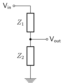
Z1 will be your speaker wire and Z2 will be the speaker. Vin will be the amplifier. If Z1 is 8 ohm as Z2, then it will dissipate half the power the amplifier delivers to the speaker! Same current goes through both resistors so the math dictages power through Z1 is Z1 * I as will Power through Z2= I * Z2.
Raise your hand if you want your speaker wire to throw away half of your power. Good, I don't see any hands raised.
For RF situations or where cables are kilometers long as is with analog telephone we have reflections to worry about so matching impedances are used as you indicate. But for audio, we do not and as such, this is absolutely wrong thing to do. Wire resistance/impedance must be kept to minimum in order to reduce its losses.
In addition to straight losses, speaker impedance varies with frequency. If the wire resistance/impedance is a significant fraction of the speaker impedance, it will server to change its frequency response which again, is a bad thing.
I suggest reading Snow's 1957 Journal of AES paper, Impedance -- Matched or Optimum? Here is the synopsis:
View attachment 23987
View attachment 23988
This dog does not hunt. It didn't in 1957, and doesn't today. Simple, basic understanding of electrical systems and transmission stipulates this.
A pleasure. I look forward to the debate.Max, very nice to see you posting here , welcome to ASR,
Thank you for taking the time to personally respond to my query.
Keith
The matching must be in the bulk of the cable itself. Not lumped at the ends. Please take a closer look at the simulations.The problem is that, as with many of the test instruments at work, I can sign it out but I'm too nervous to bring home a piece of equipment worth more than my house... Guess I could bring home a couple of cables, though, and gen up some adapters to see just how improved the sound can be with 50 GHz RF cables used for speaker wires. The sad part is those RF cables, which I always though insanely expensive at a few thousand to $10k USD or so, are cheaper than many speaker cables these days.
Wasn't it Mogami who developed speaker cables with 8-ohm characteristic impedance many years ago? 1970/1980 timeframe... Too bad speakers do not have a constant 8-ohm impedance. I actually piddled, at the behest of some friends, with matching networks to counter the speaker's impedance swings and provide a matched impedance for that cable. The matching network thoroughly corrupted the frequency response (etc.) since the speaker was designed to be driven by a regular old amplifier, e.g. a ~0-ohm voltage source, and not a matched 8-ohm source. The speakers were B&W 801, my Magnepan MG-IIIa, and Quad ESLs IIRC -- a cross section of designs. None of them responded well even with "perfect" matching. Obvious to me today, but I was in college and all things were fun to try, and I got to show my friends (and teachers) the results of my experiments.
This.Characteristic impedance is irrelevant for the wavelengths involved. You can’t change physics even if your wallet is involved.
Square wave with wide bandwidth is not a proper test unless it is band limited to the audible frequencies.
.. Too bad speakers do not have a constant 8-ohm impedance. I actually piddled, at the behest of some friends, with matching networks to counter the speaker's impedance swings and provide a matched impedance for that cable. The matching network thoroughly corrupted the frequency response (etc.) since the speaker was designed to be driven by a regular old amplifier, e.g. a ~0-ohm voltage source, and not a matched 8-ohm source. The speakers were B&W 801, my Magnepan MG-IIIa, and Quad ESLs IIRC -- a cross section of designs. None of them responded well even with "perfect" matching. Obvious to me today, but I was in college and all things were fun to try, and I got to show my friends (and teachers) the results of my experiments.
The problem is that, as with many of the test instruments at work, I can sign it out but I'm too nervous to bring home a piece of equipment worth more than my house... Guess I could bring home a couple of cables, though, and gen up some adapters to see just how improved the sound can be with 50 GHz RF cables used for speaker wires. The sad part is those RF cables, which I always though insanely expensive at a few thousand to $10k USD or so, are cheaper than many speaker cables these days.
Wasn't it Mogami who developed speaker cables with 8-ohm characteristic impedance many years ago? 1970/1980 timeframe... Too bad speakers do not have a constant 8-ohm impedance. I actually piddled, at the behest of some friends, with matching networks to counter the speaker's impedance swings and provide a matched impedance for that cable. The matching network thoroughly corrupted the frequency response (etc.) since the speaker was designed to be driven by a regular old amplifier, e.g. a ~0-ohm voltage source, and not a matched 8-ohm source. The speakers were B&W 801, my Magnepan MG-IIIa, and Quad ESLs IIRC -- a cross section of designs. None of them responded well even with "perfect" matching. Obvious to me today, but I was in college and all things were fun to try, and I got to show my friends (and teachers) the results of my experiments.
Max, these effects your referring to, do you have any measurements of the changes coming out of a speaker?A pleasure. I look forward to the debate.
You do understand about wavelength, right? This is 5 or 6 meters of wire.I am working on a full white paper on this. Just getting together the facts.
BTW why do you guys talk only about short wave transmitters when discussing impedance matching? What about the 50/60Hz grid? It would simply not work if impedance matching was not considered in the design. (I know a bit, because I have an honours-grade pass in low frequency transmission line theory)