
RandomEar
Senior Member
- Joined
- Feb 14, 2022
- Messages
- 335
- Likes
- 776
After getting a couple of weird results on my first MMM measurements, I went searching around the forums & YouTube for what went wrong. To save others from gathering various bits and pieces of info from a dozen sources, I decided to publish this quick write-up here. You can use it as a rough guide and adjust the settings to your liking.
Prepare your measurement
You are now ready to measure. Now is a good time to deactivate all EQs and filters you don't want in your measurement, if you didn't get to that before.
Perform the measurement
Congrats, you measured something using the MM method!
From this point on, the next steps depend on your goals and hardware. To create an EQ for your setup, you would go into the "EQ" window, configure your "Target Settings" and then run "Match response to target" in the "Filter Tasks" tab. The results can then be exported into different formats - "Export filter settings as text" for example results in a couple of lines which can be directly copied to an Equalizer APO config file.
Further reading:
 www.audiosciencereview.com
www.audiosciencereview.com
www.audiosciencereview.com
www.audiosciencereview.com
www.audiosciencereview.com
www.audiosciencereview.com
www.audiosciencereview.com
www.audiosciencereview.com
www.audiosciencereview.com
Prepare your measurement
- Make sure your volume is at a comfortable level for music listening (to avoid a jump scare later on)
- Consider hearing protection - things might accidentally get VERY LOUD if certain settings are wonky
- Put your measurement microphone on a monopod or selfie stick, preferrably using a shock / anti-vibration mount
- Attach your mic to the PC using a sufficiently long cable
- Open REW and configure it to use the correct mic and calibration file (for UMIK's, use the "_90°"-file)
- Open the SPL meter using the default settings (dB(Z) S)
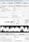
- Open the Generator and configure it as follows:
- Mode "Noise"
- Type "Pink Periodic"
- Target "Full range"
- Sequence length "64k" (default)
- Level -12 dBFS
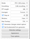
- Open the RTA window and configure the graph controls (gear symbol in the upper right) as follows:
- Mode "RTA 1/48 Octave"
- Smoothing "1/48 smoothing"
- FFT length "64k" (default)
- Averages "Forever"
- Stop at "30" to "60" (depending on your patience)
- Window "Hann" (default)
- Max Overlap "50" (default) to "75" (slightly quicker)
- Enable "Generator changes restart capture"
- Click on Appearance and adjust:
- Disable "Use bars on RTA" (optional)
- Enable "Adjust RTA levels"
- Adjust your SPL:
- Bring yourself and the mic in position, holding the mic vertical (pointing towards the ceiling)
- Start the Generator
- Adjust the volume on your system until the SPL meter shows roughly 80 - 85 dB(Z)
- Turn off the Generator
You are now ready to measure. Now is a good time to deactivate all EQs and filters you don't want in your measurement, if you didn't get to that before.
Perform the measurement
- Bring yourself and the mic in position, holding the mic vertical (pointing towards the ceiling)
- Start the Generator
- Start the measurement by clicking on the square [record] button in the upper right of the RTA window
- Slowly move the mic around your measurement position randomly
- Keep an eye on the "## averages" label in the lower left of the RTA windo. When the number of averages reaches your self-imposed limit, the measurement will stop automatically
- Turn off the Generator. Your RTA window should now look something like this:
- Copy the finished measurement to the main REW window by clicking on the "Current" button in the top center of the RTA window
- Optional: Save the measurement in the main window to avoid losing the data later on
Congrats, you measured something using the MM method!
From this point on, the next steps depend on your goals and hardware. To create an EQ for your setup, you would go into the "EQ" window, configure your "Target Settings" and then run "Match response to target" in the "Filter Tasks" tab. The results can then be exported into different formats - "Export filter settings as text" for example results in a couple of lines which can be directly copied to an Equalizer APO config file.
Further reading:
Room Measurement Tutorial for Dummies Part 1
There are few more things transformative in audio than learning how room acoustics works. You never look at any system the same again. Like moving from film photography to digital, measurements give you instant feedback on what your system is doing. Even if you choose to not make any changes...
www.audiosciencereview.com
Room Measurement Tutorial for Dummies Part 2
Room Measurement Tutorial for Dummies Part 2: Selecting a Measurement Microphone I hope everyone has read the first part of this tutorial on downloading and installing Room EQ Wizard. Here is the link to that if you missed it...
www.audiosciencereview.com
Help with REW RTA measurement using the MMM method
Greetings, I have recently acquired a UMIK-1 and started learning how to use REW for measurement and correction. First I did the swipe based measurement in a single position, using the excellent guide at and the measurement curve made a lot of sense, in terms of levels and slopes. Then I...
www.audiosciencereview.com
REW-Moving Microphone Method Help
Hello. I have used REW some but saw that some people use a moving microphone method to get a quick spacial average. The video I watched made it look quick and easy. I was able to to fumble my way through partially, but the graph doesn’t look like frequency response. Anyone know the steps to get...
www.audiosciencereview.com
Moving mic vs. averaged vs. single point measurements - which is better?
AFAIK there are three ways we can measure room response for loudspeakers: - Maximum Length Sequence (MLS), Exponential Sine Sweep (ESS) or single point sweep: The mic is set up at the listening position, and a single sweep is taken. - Averaged: The mic is set up at various points around the...
www.audiosciencereview.com
Attachments
Last edited:
