Outdoor cable has weather and UV ptotection. And then theres direct burial cable that has special insulation and is full of moisture repelling gel. The amount of engineering thats gone into "regular" (not audiophool) cable is enormous, many orders of magnitude more than one uneducated guy at BSaudio. To think that these real cable companies (mogami, beldon, canare, etc) dont know how to make an audio cable is ridiculous.

-
WANTED: Happy members who like to discuss audio and other topics related to our interest. Desire to learn and share knowledge of science required. There are many reviews of audio hardware and expert members to help answer your questions. Click here to have your audio equipment measured for free!
You are using an out of date browser. It may not display this or other websites correctly.
You should upgrade or use an alternative browser.
You should upgrade or use an alternative browser.
Technical Article: Does Audio Cable Skin Effect Matter
- Thread starter DonH56
- Start date
OP
- Thread Starter
- #62
I have not been online much, busy... Are we now debating the skin depth in vinyl? ")
I don't remember the numbers off-hand but I seem to recall that when you actually calculate the cross-sectional area at 20 kHz you are still much better off using a conventional large (e.g. 12 AWG) cable than trying to mess around with Litz wires. There was also the contention that there was enough phase shift to be audible due to the difference in effective resistance from say 20 Hz to 20 kHz. Of course they presented numbers as ratios and fancy plots scaled to make it look like a huge problem whereas it was actually tiny fractions up in the MHz region. I have seen that argument made today; too bad more of us aren't trained in basic circuit theory. Litz wire was popular in the late 70's and early 1980's; I would have hoped that myth would have died out by now. Should have known better. Wire is cheap in bulk so dealers and manufacturers can make a fortune if their marketing is good enough.
I don't remember the numbers off-hand but I seem to recall that when you actually calculate the cross-sectional area at 20 kHz you are still much better off using a conventional large (e.g. 12 AWG) cable than trying to mess around with Litz wires. There was also the contention that there was enough phase shift to be audible due to the difference in effective resistance from say 20 Hz to 20 kHz. Of course they presented numbers as ratios and fancy plots scaled to make it look like a huge problem whereas it was actually tiny fractions up in the MHz region. I have seen that argument made today; too bad more of us aren't trained in basic circuit theory. Litz wire was popular in the late 70's and early 1980's; I would have hoped that myth would have died out by now. Should have known better. Wire is cheap in bulk so dealers and manufacturers can make a fortune if their marketing is good enough.
Last edited:
Speedskater
Major Contributor
Cyril Bateman (RIP) did a three part magazine article in 1996. Part of that article was about some amp, cable and speaker combinations oscillating in the megahertz range.It seems to me that the reason why some amplifiers could self-oscillate from litz-type speaker wire is because of parasitic capacitance or parasitic inductance, induced from having those smaller wires in close proximity.
It could be that some power cables are used as speaker cables. That could also be the cheapest solution and would work fine if the conductors are spaced apart for most of the length, and the total gauge provides the right resistance from what I can see.
So that's why I pointed out that coupling multiple smaller gauges together could be the cheapest option and a way to deal with skin effect at the same time, which is also a nice way to actually use the copper that was paid for.
Like this quote. You just can't make this up or then again, the manufacturers can. This manufacturer called Atlas Cables speaks on velocity of propagation. But I also doubt whether people can hear a difference when the signal travels at 50% or more of the speed of light. Maybe, it was just a typo and they meant velocity of propaganda...Are we now debating the skin depth in vinyl?
"Cable losses are therefore frequency dependent, with the high frequencies undergoing the most loss. This is known as the ‘skin effect.’ It causes a great deal of controversy in audio circles as many argue that it is only relevant at high frequencies which are beyond the range of human hearing. However, that's not entirely true, because conductor resistance starts to increase due to the skin effect at around 20 kHz. It’s high frequencies which create timbre, ambience and a clear treble.
"High frequency signals occupy the periphery of a conductor (see above). Poor quality dielectrics (insulation materials) reduce the velocity of this signal, resulting in a sound which is biased towards the low and mid frequency regions of the audio spectrum. Thus, a poor quality sound often accompanies the use of a cable with a poor quality dielectric."
Run, don’t walk.Like this quote. You just can't make this up or then again, the manufacturers can. This manufacturer called Atlas Cables speaks on velocity of propagation. But I also doubt whether people can hear a difference when the signal travels at 50% or more of the speed of light. Maybe, it was just a typo and they meant velocity of propaganda...
"Cable losses are therefore frequency dependent, with the high frequencies undergoing the most loss. This is known as the ‘skin effect.’ It causes a great deal of controversy in audio circles as many argue that it is only relevant at high frequencies which are beyond the range of human hearing. However, that's not entirely true, because conductor resistance starts to increase due to the skin effect at around 20 kHz. It’s high frequencies which create timbre, ambience and a clear treble.
"High frequency signals occupy the periphery of a conductor (see above). Poor quality dielectrics (insulation materials) reduce the velocity of this signal, resulting in a sound which is biased towards the low and mid frequency regions of the audio spectrum. Thus, a poor quality sound often accompanies the use of a cable with a poor quality dielectric."
killdozzer
Major Contributor
So that if you decide to let a thunder go through your speaker cables you won't have any resistance increase?a way to deal with skin effect
You seem to be attached to this "problem" and somehow resist the possibility that it is NOT a problem. Almost like you would miss it. Also "info" you quote here seems to have you contaminated with a huge amount of marketing hype. The seller of overpriced cables is not your friend. He is just trying to sell you more than you need. People here telling you you don't have an actual problem, gain nothing from it.
There's always that.
killdozzer
Major Contributor
Don't be like that. It's never a waste of time for everyone. All sorts of different members read articles here. But if you have someone who yearns to have a problem, explanations are just robbing him of that. I still think it's a minority.Posting articles here is clearly a waste of time.
I like the term FUD that I learned in this thread. Fear, uncertainty and doubt. Also learned other things by talking about it here, nothing wrong with that.So that if you decide to let a thunder go through your speaker cables you won't have any resistance increase?
You seem to be attached to this "problem" and somehow resist the possibility that it is NOT a problem.
Among other things I learned that resistance is what matters with speaker wire, despite of claims to the contrary by manufacturers and I am now no longer worried about what I discussed earlier in the thread.
F
freemansteve
Guest
Where are my old RF ear-trumpets when I need them?
The main thing that I hope was your take-away is that fashion audio manufacturers and dealers LIE, especially when it comes to anything on the electronics end (including wires). They're very good at taking something real but irrelevant and using it to justify the vital importance of their products.I like the term FUD that I learned in this thread. Fear, uncertainty and doubt. Also learned other things by talking about it here, nothing wrong with that.
Among other things I learned that resistance is what matters with speaker wire, despite of claims to the contrary by manufacturers and I am now no longer worried about what I discussed earlier in the thread.
So if you look up "skin effect" (as the example at hand), you see that it's a real thing, but the vast majority of audio consumers and enthusiasts don't know enough about electricity and magnetism to make the jump to "I'm not running a VHF transmitter." It's even worse when they use math to lie: "The impedance of the cable doubles from bass to treble, and that's a 6dB difference!" The enthusiast will not understand that this is equivalent to worrying about the effect of dust particles landing on you when you're weighing yourself, but will jump to "OMG, I'll lose 6dB of treble!"
There's a special place in Hell for the rip-off artists who profit from spreading ignorance.
Between 8th and 9th Dante's circles, depending on if they just lie or use misleading measurements and calculations to lie.There's a special place in Hell for the rip-off artists who profit from spreading ignorance.
OP
- Thread Starter
- #72
The skin depth equation may not be reliable at such low frequencies, but let's pretend that it is. Skin depth is about 0.82" at 10 Hz and 0.018" at 20 kHz. The area of a circle is A = pi*r^2 and for an anulus it is A = pi*(R^2 - r^2) where R is the outer radius and r the inner radius.
12 AWG wire is about 0.081" in diameter and the DC resistance (DCR) is about 1.6 m-ohm/foot, or about 0.016 ohms for 10', and thus about 0.032 ohms for a speaker cable (two wires). The capacitance of a pair depends upon the insulation thickness and construction style (some spae the conductors further apart, reducing the capacitance). A quick look shows a range of about 10 to 20 pF/foot, compared to about 30 pF/foot for a 75-ohm coax interconnect, so that range seems reasonable (about half that of coax). I happen to have a reference showing 19.5 pF/foot for shielded 12 AWG wire so let's use 15 pF for typical unshielded 12 AWG speaker cables (middle of the range). That is 150 pF for a 10' pair.
At 10 Hz the skin depth exceeds the cable's diameter so the entire cable is used, and DCR = ACR = 32 m-ohms. The area is A = pi*(0.081/2)^2 = 0.00515 sq inch for a single wire. We can ratio that to the anulus area to estimate the resistance of the anulus.
At 20 kHz I'll use the skin depth to find the cross-section area A = pi*[(0.081/2)^2 - (0.081/2-0.018)^2] = 0.00356 sq inch. The outer radius is the entire wire as above, and the inner radius is the outer radius less the skin depth.
Now the pair of 12 AWG wires 10' long is 32 m-ohms (0.032 ohms) at DC and the same at 10 Hz. At 20 kHz, we can ratio the cross-sectional area to estimate the resistance at 20 kHz as 0.032 ohms * 0.00515/0.00356 = 0.0463 ohms. For marketing, that is a 45% increase in resistance, or 3.2 dB. Seems huge, eh?
But look at the real-world implications... Aside from the output impedance of the amp, which is 80 m-ohms for a damping factor of 100 (and usually much, much lower at 20 kHz so output impedance is much, much higher), there is the crossover and speaker impedance in the picture, all of which are likely much higher than that of the wire at either frequency. But since frequency response is commonly cited, we can look at that.
I'll do a lumped model because it is easier for a back-of-the-envelope calculation. In the real world, resistance and capacitance is distributed along the length of cable, so my simple model will be slightly off. Feel free to fire up your EM simulator or measure on a VNA if you want a closer result.
Conductance is at the surface so capacitance to first order is the same at either frequency. At 10 Hz, the effective cable time constant is R*C so 0.032 ohms * 150 pF = 4.8 ps. At 20 kHz, it has risen to 0.0463 ohms * 150 pF = 6.9 ps, an increase of 2.1 ps. A ps is 10^-12 seconds. If your system has 100 kHz bandwidth, that equates to a first-order time constant of around 2.2/(2*pi*f) = 2.2/(2*pi*100e3) = 3.5 us, about 435,783 times larger than the change due to skin effect in the cable. I am pretty sure I could not hear the difference. I started to calculate phase shift and such but it's just not worth my time and I have to get back to work.
Check my math, I was in a hurry - Don
About right. Below is from a Belden blog post on the same topic (to debunk the same myth).

mhardy6647
Grand Contributor
- Joined
- Dec 12, 2019
- Messages
- 11,465
- Likes
- 24,900
Where are my old RF ear-trumpets when I need them?

Did they keep the birdshit?
mhardy6647
Grand Contributor
- Joined
- Dec 12, 2019
- Messages
- 11,465
- Likes
- 24,900
Used for fine tuning, methinks.Did they keep the birdshit?
This topic got me thinkin' of an artifact less than a mile from where I sit typing this...

(photo I took in April 2014, shortly after we moved to NH 'full time')
One of the old AT&T "long lines" relay towers.
My late father-in-law was a "telephone pioneer" (radar, too) and worked for AT&T for his whole career.
He (and my late mother-in-law) retired to this same tiny hamlet where we now live, on the other side of the hill from that tower; just a couple of miles from here (if that) as the microwave travels.
I fell in love with this area the first time I visited their place, and vowed to retire here (which we did) -- before I'd even had my first 'real' job.
Last edited:
My favorite DIY cable brand.About right. Below is from a Belden blog post on the same topic (to debunk the same myth).
View attachment 195195
F
freemansteve
Guest
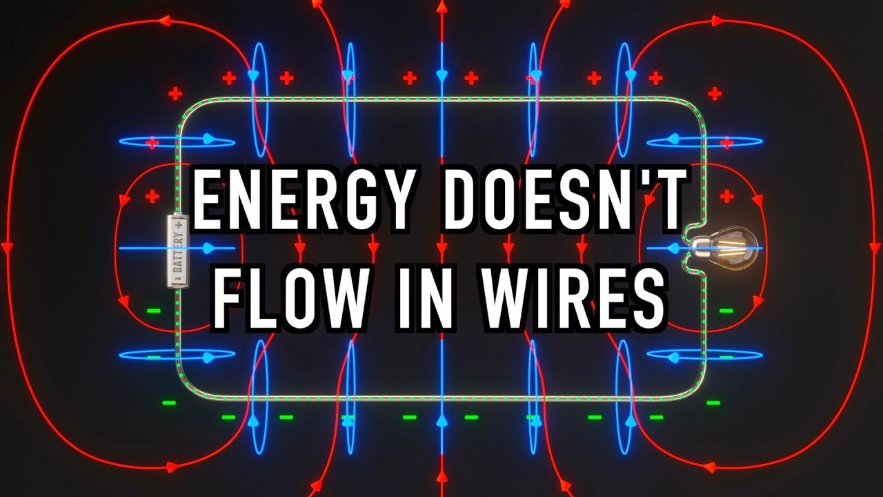
Also interesting, but not on really on-topic...
 www.veritasium.com
The Big Misconception About Electricity — Veritasium
The misconception is that electrons carry potential energy around a complete conducting loop, transferring their energy to the load.
www.veritasium.com
Also interesting, but not on really on-topic...
The Big Misconception About Electricity — Veritasium
The misconception is that electrons carry potential energy around a complete conducting loop, transferring their energy to the load.
Has it's own thread.

Speaker wires don't carry any energy (power).
Tell them when they try to sell you expensive cables. Very nonintuitive but true. https://www.youtube.com/results?search_query=The+great+misconcception+wire
audiosciencereview.com
Similar threads
- Replies
- 37
- Views
- 7K
- Replies
- 0
- Views
- 388
- Replies
- 48
- Views
- 13K
- Replies
- 4
- Views
- 2K
- Replies
- 30
- Views
- 2K