• WANTED: Happy members who like to discuss audio and other topics related to our interest. Desire to learn and share knowledge of science required. There are many reviews of audio hardware and expert members to help answer your questions. Click here to have your audio equipment measured for free!

Step Response: Does It Really Matter?

dougi

Addicted to Fun and Learning
Joined
May 31, 2020
Messages
845
Likes
767
Location
ACT, Australia
This is kind of in a place I can't discuss presently, but with an FIR filter you can do many things you can not do with an IIR filter.
Understood, so the DSP in the NAD may not support as many FIR filters (or taps or whatever the case is) as the MiniDSP Flex can, and DIRAC is told this and does as much as the NAD is able to implement perhaps?
 

Keith_W

Major Contributor
Joined
Jun 26, 2016
Messages
2,660
Likes
6,064
Location
Melbourne, Australia
This is kind of in a place I can't discuss presently, but with an FIR filter you can do many things you can not do with an IIR filter.

My understanding of FIR vs. IIR filters is quite rudimentary, as in all I know is what they are. Can you expand a little on this please? Or point to some resources?

(Not asking you to spill any beans on Dirac, I understand if you are under some kind of NDA).
 

j_j

Major Contributor
Audio Luminary
Technical Expert
Joined
Oct 10, 2017
Messages
2,282
Likes
4,792
Location
My kitchen or my listening room.
Understood, so the DSP in the NAD may not support as many FIR filters (or taps or whatever the case is) as the MiniDSP Flex can, and DIRAC is told this and does as much as the NAD is able to implement perhaps?
I've no direct knowledge of any of those products, sorry, well, except that the miniDSP is pretty cheap, and an rPi with a decent interface is pretty cheap, too.
 

j_j

Major Contributor
Audio Luminary
Technical Expert
Joined
Oct 10, 2017
Messages
2,282
Likes
4,792
Location
My kitchen or my listening room.
My understanding of FIR vs. IIR filters is quite rudimentary, as in all I know is what they are. Can you expand a little on this please? Or point to some resources?

(Not asking you to spill any beans on Dirac, I understand if you are under some kind of NDA).
Somewhere on here are, I think, some discussions on properties of FIR's. FIR's are, effectively, simply convolving by an impulse response. While IIR's have to be stable, which means that the poles must be inside the unit circle (the roots of the pole polynomial), and as a result have a strong minimum-phase character (zeros can be anywhere, and do not have to be inside the unit circle, i.e. minimum phase) and have, strictly speaking an infinite length (that dies to below noise floor pretty quickly, of course), FIR's can be minimum phase, constant delay, maximum phase, or anything in the middle. So for an FIR, it is possible to have a variety of impulse responses that provide exactly the same amplitude characteristic, but do not have the same PHASE characteristic. Maybe this is a discussion for its own thread, if somebody better at the search here than I can't find the old one?

Dirac is not involved here, I must be careful not to let out my own design methods. I've found much to criticize in some crossover designs. Hopefully at some point I can say more.

A few people have heard ours, but we aren't in the speaker business, we just built some so as to have control over the rest of our experimental setups. @amirm has heard some of our stuff, as have a few other people here.
 

j_j

Major Contributor
Audio Luminary
Technical Expert
Joined
Oct 10, 2017
Messages
2,282
Likes
4,792
Location
My kitchen or my listening room.
I found one mention, but it's kind of obscure and buried in the room correction thread. This shows 3 different impulse responses with mathematically identical amplitude response, but radically different phase responses. This is something one can do in FIR that is very difficult in an IIR (You can do this to the zeros in an IIR, but not the poles)
src1_9_16(2).jpg
 

songOVERsound

Active Member
Joined
Mar 11, 2023
Messages
105
Likes
53
For a person who can’t dive into all these fine details, is the take-away that Trinnov is the best partly because it uses FIR?
 

neRok

Senior Member
Joined
Oct 7, 2022
Messages
304
Likes
175
Location
Australia
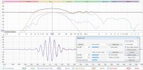
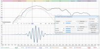
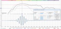
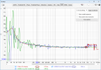
maybe the best solution is a look on group delay at diffrent volumes ?. I have add screenshots of a cheap 9 eur headphone for compare. it is measure too at 1 cm distance. but there can see on LP 6 GD change lots more than on JBL. and on LP6 group delay change much more depend on volume.View attachment 143826View attachment 143827View attachment 143828View attachment 143830View attachment 143831
I got on to this thread somehow. I've read a bit of the start and end. I get the discussion regarding bandwidth and high/low pass filter effects on the impulse/step response, and how that means the problems bennybbbx was inferring from the step response weren't proper assesements (the problems being that Kali LP6 have slow speed and ITD problems). But in these group delay screenshots you can see that the Kali have far more GD variance than the JBL he was comparing to (the range is worse, and the slope is worse). Someone else showed data that said sharp GD changes in the 1kHz-4kHz range is bad (eg1, eg2), and the Kali seems to have a lot of those. What is causing these wild peaks on the Kali? Is this because of the DSP EQ they have applied, and perhaps they haven't considered the GD affects?

gds.png
 
Last edited:

bennybbbx

Addicted to Fun and Learning
Joined
May 27, 2020
Messages
691
Likes
124
Location
germany
so fast changing can also see on envelope(ETC) . it can show in impulse tab. seem speaker testers and developer do not check that. also there is not much docu found. there can read it show room resonances and my measure show it seem also show good speaker case resonances. now i have treated my room partly and buy a yamaha hs 5. this sound best in tsereo image and bass precision. in the etc there is no false peak higher as 25%. other speakers reach false peak level of over 35% . if klippel can show envelope etc maybe more usefull as group delay or step response. i like see how it look with more speakers

in 80 cm distance measure mic and speaker on same position. seem the 25% peak at 600 µsec is room resonance and the 18% peak at 1.7 ms too. because this peak can see on other speakers too

Yamaha hs 5

yamaha hs 5 etc.jpg


JBL 104

jbl 104 etc.jpg


Kali LP6

kali lp6 etc.jpg


focal alpha 65 evo

focal alpha 65 eco etc.jpg


here are the measures for download and more screenshot and audio compare mp3
 
Last edited:

neRok

Senior Member
Joined
Oct 7, 2022
Messages
304
Likes
175
Location
Australia
What is causing these wild peaks on the Kali? Is this because of the DSP EQ they have applied, and perhaps they haven't considered the GD affects?
I've just finished testing and posting about the GD of my Kali IN8 V2. Below I have included a quote of the relevant section.

Those sweeps were all to 2kHz, so then I did a full 20Hz-20kHz sweep of the woofer and the coax (mic at about same position = 3oclock + 1cm).
06 - Woof+Coax GD.png

You will see on those tests that when I sweep close to the woofer, the GD is quite smooth. But when I measured close to the coax speaker, there appears to a sort of "comb filter" in the GD where the woofer is active. I wonder if this is what happened to the LP6 measurements?

Here is the ETC plot of my woofer+port sum VS the "perfect impulse" of the same filters (normal butterworth filters);
11 - ETC.png

It seems to be correct. The red spikes before the blue line would just be because the sweep has recorded more than just the woofer+port (I swept to 2kHz, but the woofer is crossed at 280Hz). The bulk of the rises are aligned, so that suggests the GD is within normal bounds too, and that there isn't any "speed" problems. The blip at ~8ms is a bit weird, but could just be something from my environment (the desk reflection for example).

I've attached the sweeps in case bennybbbx wants to review them for himself.
 

Attachments

  • Kali IN8 V2 Tests.zip
    2.3 MB · Views: 28

bennybbbx

Addicted to Fun and Learning
Joined
May 27, 2020
Messages
691
Likes
124
Location
germany
I've just finished testing and posting about the GD of my Kali IN8 V2. Below I have included a quote of the relevant section.


You will see on those tests that when I sweep close to the woofer, the GD is quite smooth. But when I measured close to the coax speaker, there appears to a sort of "comb filter" in the GD where the woofer is active. I wonder if this is what happened to the LP6 measurements?

You have link the attachment of my measure but not the post. normaly i write in post how i measure. I am 99% sure that i measure 10 cm away(to avoid room influenece) in middle of speaker(not system) so angle to woofer and tweeter is same. when you tell me the post i can faster see posts before where i have written how i measure

your measure of etc is strange. normaly the peak if speaker have less bass as jbl 104 or speaker have much bass as focal alpha 65 is near same and shorter as 0.1 msec to go down to 60% . in older measures in untreated room it only have larger false peak level. so better measure 10 cm away


how much measure distance you have for your etc ? or maybe need measure allways full range from 20 hz to 20 khz . etc measure is also best to avoid more room reflections when do 10-20 cm away from speaker and angle from woofer to tweeter is same. so mic is in middle.

but my measure of all at same pos is at distance 80 cm was enough to see that HS 5 is much better

I have done now a 10 cm measure . later reflections are reduce but this measure also show clear. if false peaks happen more than 25% it is case resonance

hs5 etc 10 cm away.jpg
 

neRok

Senior Member
Joined
Oct 7, 2022
Messages
304
Likes
175
Location
Australia
You have link the attachment of my measure but not the post.
My post 428 linked to your post 374.

how much measure distance you have for your etc ? or maybe need measure allways full range from 20 hz to 20 khz .
Very close to keep the results as "pure" as possible (unpolluted by the room and the coax speaker), and I used acoustic timing ref. I was only interested in the woofers GD, hence originally doing short sweeps to 2kHz, but then I checked the coax with full sweeps anyway.
measure.jpg

your measure of etc is strange. normaly the peak if speaker have less bass as jbl 104 or speaker have much bass as focal alpha 65 is near same and shorter as 0.1 msec to go down to 60%
Like other people have been saying, it's all about the bandwidth of the measurement/impulse, because high frequencies "bunch up" at the start. If you 1) measure the woofer only, 2) sweep less frequency range, or 3) low pass filter your results, it will look more like the purple example below rather than the green sample.
20 - filters.png

Maybe this video will help you understand why the impulse "bunches up".

If you truly are sensitive to group delay, then don't by ported speakers because the port adds group delay AND they need a HPF to protect the driver at the tuning frequency, which adds more GD when using min-phase filters like BW and L-R. So either go sealed without HPF, or use something with "linear phase" filters (FIR filters that maintain the phase).
 
Last edited:

bennybbbx

Addicted to Fun and Learning
Joined
May 27, 2020
Messages
691
Likes
124
Location
germany
My post 428 linked to your post 374.


Very close to keep the results as "pure" as possible (unpolluted by the room and the coax speaker), and I used acoustic timing ref. I was only interested in the woofers GD, hence originally doing short sweeps to 2kHz, but then I checked the coax with full sweeps anyway.
View attachment 310432


Like other people have been saying, it's all about the bandwidth of the measurement/impulse, because high frequencies "bunch up" at the start. If you 1) measure the woofer only, 2) sweep less frequency range, or 3) low pass filter your results, it will look more like the purple example below rather than the green sample.
View attachment 310431

Maybe this video will help you understand why the impulse "bunches up".

If you truly are sensitive to group delay, then don't by ported speakers because the port adds group delay AND they need a HPF to protect the driver at the tuning frequency, which adds more GD when using min-phase filters like BW and L-R. So either go sealed without HPF, or use something with "linear phase" filters (FIR filters that maintain the phase).

in previous posts i write i do this GD measures 1 cm away. simular you do, ok thats good. now i do the same with the HS5 . it have mostly lots smaller group delay also to your estimate kurve . see screenshot and my attach mdat .there is also a measure with my EQ at 86 hz and 106 hz you can see some peaks. my other speakers i maybe measure again but i dont think that result change alot in compare to older

hs 5 bass 1 cm away.jpg


I EQ with hearing only what i think sound better. and look what i eq at my room mode 80 hz . a setting that let the group delay go near 0 . but for 110 hz i need increase level to sound better. this inrease group delay. so can say EQ boost increase group delay EQ cut decrease group delay . tracks dsp have IIR filter i guess

hs 5 with eq.jpg


with the new position (see hs5 thread) i need not change 1 khz peak . so i only need eq this to get no strange feeling in ears or ear pain also after longer hear. maybe see GD of such a measure of a high expensive speaker if they are better as HS 5

hs 5 eq settings.jpg


EDIT 3 I notice you use var smoothing . I do the same change not much but to be same here is screenshot. in mdat dont forget to switch to var smothing when compare

hs 5 1 cm measure var.jpg


science tell that hearing work with ERB smothing. so here is compare of this

erb smoothing 1 cm hs 5.jpg
 

Attachments

  • hs 5 1cm woofer.zip
    1.1 MB · Views: 29
Last edited:

bennybbbx

Addicted to Fun and Learning
Joined
May 27, 2020
Messages
691
Likes
124
Location
germany
Like other people have been saying, it's all about the bandwidth of the measurement/impulse, because high frequencies "bunch up" at the start. If you 1) measure the woofer only, 2) sweep less frequency range, or 3) low pass filter your results, it will look more like the purple example below rather than the green sample.

there is not find GD plots of (good) speaker or any speaker. https://speakerdesignworks.com/group_delay.html

the curve you create does there too not fit. I dont care what other say it is pysical logic that a stronger magnet motor can be more precise. and in this page you can see the grpup delay depend in Bass from the QTC. so wy no speaker tester show Group delay ?. Ironic: Is there a Hifi Mafia that forbid that and speakers are only designed that they look good in FR and how good they are with transients is ignore or the GD delay :D . on very old speaker tests in a german magazine are bursts tests . this is also good to show which is the better speaker this also not fit your curve https://www.fairaudio.de/lexikon/gruppenlaufzeit/
 

bennybbbx

Addicted to Fun and Learning
Joined
May 27, 2020
Messages
691
Likes
124
Location
germany
here is step response of kali lp 6 V1 focal alpha 65 evo and yamaha HS 5 . you can download mdat on HS5 test page and audio to compare bass transients. microphone and speaker are all same position. there can see that the speaker with the most bass the focal alpha 65 evo have the fastest rise time of 2. peak. so it depend not much on bass range. hs5 is a little slower have lower bass, but it have not so much waves in the step response. seem better when there is less waves in the step response. hs5 sound best of all most noticable in bass transients that are in range 80-200 hz

step response all same position.jpg
 

Holmz

Major Contributor
Joined
Oct 3, 2021
Messages
2,020
Likes
1,242
Location
Australia
there is not find GD plots of (good) speaker or any speaker. https://speakerdesignworks.com/group_delay.html

the curve you create does there too not fit. I dont care what other say it is pysical logic that a stronger magnet motor can be more precise. and in this page you can see the grpup delay depend in Bass from the QTC. so wy no speaker tester show Group delay ?. Ironic: Is there a Hifi Mafia that forbid that and speakers are only designed that they look good in FR and how good they are with transients is ignore or the GD delay :D . on very old speaker tests in a german magazine are bursts tests . this is also good to show which is the better speaker this also not fit your curve https://www.fairaudio.de/lexikon/gruppenlaufzeit/

Yes people have a distaste for time domain, and even in the frequency domain like to throw out the phase and just look at amplitude.
 

pma

Major Contributor
Joined
Feb 23, 2019
Messages
4,608
Likes
10,779
Location
Prague
Filters, IR/step responses - we may create almost anything in the digital domain :)

2sampl_48_amplphase.png

corresponding time responses
2sampl_48_IRstep.png


--------------

2sampl_96_amplphase.png

corresponding time responses
2sampl_96_IRstep.png
 

BDWoody

Chief Cat Herder
Moderator
Forum Donor
Joined
Jan 9, 2019
Messages
7,082
Likes
23,538
Location
Mid-Atlantic, USA. (Maryland)
I dont care what other say it is pysical logic that a stronger magnet motor can be more precise.

Benny, we've been down this road a few times, and we're not doing it again.
 

neRok

Senior Member
Joined
Oct 7, 2022
Messages
304
Likes
175
Location
Australia
so wy no speaker tester show Group delay ?. Ironic: Is there a Hifi Mafia that forbid that and speakers are only designed that they look good in FR and how good they are with transients is ignore or the GD delay :D
I think it would be good to see too. If 2 speakers have comparable FR, max SPL, features, cost, etc - then GD would be a good differentiator because it reflects driver quality, cabinet design (ported vs sealed, volume vs tuning freq), and filter affects. I think GD would be better to see than Step/ETC because it specifically shows 1 thing, whereas Step/ETC can look 1 way but actually be 2 different things.

I dont care what other say it is pysical logic that a stronger magnet motor can be more precise.
Maybe? I don't know enough about that side of things. Thinking about it, say there are 2 woofers that are the same except 1 has a stronger magnet. If you were to put equal voltage to each woofer, wouldn't that mean the stronger one would be louder (because the stronger magnet would react with more force against the voltage)? So to have the same SPL, wouldn't the stronger one need less voltage? And maybe that comes with other drawbacks? Is that what QTC measures as a ratio?

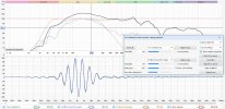
Anyway, as an experiment I thought to check the "filtered impulse" to see if there was any difference between HS5 vs IN8 whilst ignoring GD, and it seems there is a slight difference.

First I compared each speaker to a dirac impulse at a frequency they both operate strongly at;
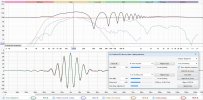
01 - dirac vs hs5 - 135Hz  align+filter.jpg 02 - dirac vs in8 - 135Hz  align+filter.jpg

Is the dirac impulse "perfect" when looked at in this regard? Because the HS5 seems to "build up" quicker than it, and "let down" quicker too. Is that indicitive of an overly strong magnet?

Comparing the 2 speakers to each other at the same frequency;
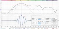
03 - hs5 vs in8 - 135Hz  align+filter.jpg

REW aligned them so that their 100% peaks were inline. This also shows the HS5 building up quicker and letting down quicker. Maybe this is splitting hairs, but the HS5 might be better, because the HS5 only has 2 peaks over 90% (-1 and 0) whereas the IN8 has 3 (-1, 0, and +1).

Maintaing that alignement but looking at different frequencies;
  • 100Hz looks similar: 04 - hs5 vs in8 - 135Hz align + 100Hz filter.jpg
  • 170Hz is similar, but HS5 is getting worse (nearly 3 over 90%) whilst IN8 has improved (only 2 over 90% now): 04 - hs5 vs in8 - 135Hz align + 170Hz filter.jpg
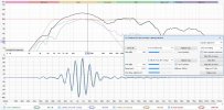
  • 200Hz shows HS5 has gotten worse with 3 peaks over 90%: 04 - hs5 vs in8 - 135Hz align + 200Hz filter.jpg
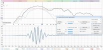
The alignment was starting to get off at 200Hz, so I let REW re-align them;
  • At 200Hz it now looks like IN8 builds up faster and lets down faster: 05 - hs5 vs in8 - 200Hz align + 200Hz filter.jpg
  • 135Hz looks different when viewed this way: 05 - hs5 vs in8 - 200Hz align + 135Hz filter.jpg
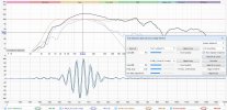
I thought maybe that wasn't the "fairest" alignment, so I manually set this one;
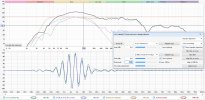
06 - hs5 vs in8 - 200Hz manual + 200Hz filter.jpg 06 - hs5 vs in8 - 200Hz manual + 135Hz filter.jpg

So I don't know if everything I've just done is actually showing magnet differences, because they seem to swap between 2 and 3 strong peaks. If 2 strong peaks was indicitive of better, than neither is always better.
 

j_j

Major Contributor
Audio Luminary
Technical Expert
Joined
Oct 10, 2017
Messages
2,282
Likes
4,792
Location
My kitchen or my listening room.
Maybe? I don't know enough about that side of things. Thinking about it, say there are 2 woofers that are the same except 1 has a stronger magnet. If you were to put equal voltage to each woofer, wouldn't that mean the stronger one would be louder (because the stronger magnet would react with more force against the voltage)? So to have the same SPL, wouldn't the stronger one need less voltage? And maybe that comes with other drawbacks? Is that what QTC measures as a ratio?

Alas, one does not follow the other. When you use a "stronger magnet" without any other differences, assuming that the magnetic circuit isn't saturating or anything disturbing, that means you also induce more back EMF into a voltage source, which changes pretty much everything. It makes the driver more damped, for instance, but since part of your goal is to have the RIGHT damping to get the desired response from the combined system, that can very well be worse.

SPL is a result of the entire system, not just the driver.

This is just the tip of the iceberg. I will say that it is quite possible to have an overdamped woofer, for sure, I've used many, and had to use electronic compensation to get what I needed from the source.
 
Top Bottom