• WANTED: Happy members who like to discuss audio and other topics related to our interest. Desire to learn and share knowledge of science required. There are many reviews of audio hardware and expert members to help answer your questions. Click here to have your audio equipment measured for free!

Small 2-way speakers with linear on-axis and power response characteristics (Scan Speak and SB Acoustics drivers). H&V off-axis measurements included

Solen is out of stock on the driver. So I'm in limbo atm.

Attachments​

  • IMG_5001.jpg
    IMG_5001.jpg
    669.4 KB · Views: 28

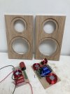
Is this an oak panel? Will it be just for the front or for the entire housing? With these high quality filter components it is worth considering building a separate crossover housing with a transparent top :)
 
It's Manitoba Elm. The rest will be top grade 3/4" ply and an inner brace. I'll put the XO inside, with so many speakers now, room space is at a premium.
 
Solen is out of stock on the driver. So I'm in limbo atm.
Are you in Canada or U.S.?

If US, you might consider ordering from soundimports.eu in Europe. The shipping costs are quite modest (~$26) despite being very fast (4-5 days). Both drivers are in stock, and notably lower price than Solen, so your total cost w/ shipping is likely lower at soundimports than Solen.

The math isn't quite as good for Canada, but may still make sense, depending on your province.
I'm in Canada. Solen has the tweeters on hold for me and they expect the woofer in early August.
 
Created an account just to read up on this design and start my first DIY speaker project! Very helpful going through everyone's builds so far. As a beginner to circuits and a self-certified dummy, would anyone be willing to post closeups of their crossover connections? Just want to make sure I'm getting it right, it'll be my first time soldering as well.
 
I appreciate the responses, but your objectives seem different from mine. You both seem heavily involved in DIY speakers; I expect the two Mechano23's to be the only speakers I will ever build.

So, to clarify: My only purpose in measuring impedance is to confirm that I have wired two Mechano23 crossovers properly. My cost in using Audio Judgement's approach is about $6.

The DATS is $125, the audio interfaces I could easily find were that or more.
-
Will the simple and cheap Audio Judgement approach confirm my wiring?
Just wire them correctly. The speaker terminals are marked + and -. The capacitors are unpolarized, the speaker terminals are red and black. Where is the possibility of wiring anything incorrectly? If the components are wired really incorrectly no tests will exactly determine the specific errors made. You can do it man!
 
There was a concern (link) that Mechano23 crossover was tuned to the specific drivers copies and the results with other driver samples, especially coming from different production lots, might be significantly different.
I've built another Mechano23 pair, the drivers were purchased from the same source but 1.5 year later so they're possibly from different production lot.

View attachment 383034
Gated spl measurements (>300Hz) are very similar. The measurement curves are shifted for better readability, the lower pair is the original, the upper is new.

View attachment 383032
The impedance characteristics look different on the LF side (higher fs of new midwoofers?).

Good correlation overall but it's hard to call it a definitive conclusion.

BTW, the enclosures are bit different No change in external dimensions but panels and joints are modified.
View attachment 383035 View attachment 383033
Definitely looks like higher Fs. Does the second set got as much play time as the original woofers. I have a few SB midwoofers pairs and they took a while and 'some bass' to stabilize. They dropped the Fs by a few Hz after the initial 'brake in'. But some of them were still quite 'off' comparing to factory data and then I noticed that other people also measured T/S data to be somewhat similar to mine. Also there's something like 10% industry tolerance between batches. Did you measure the second set before installation ?
 
Great job! I'm glad that you liked the design.

You may also try to experiment with closer wall placement or even putting them on a shelf.
I have them placed a few cm from the side walls and about 1 m from the back wall, turned towards the listening place. It was determined more by the room topology than a sound optimum but it works quite well.

Did you have a chance do take any measurements? Even simple impedance sweep can be very useful. If by chance any connection in the crossover is misplaced or missing it creates evident change in the impedance graph.
Hi,
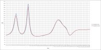
Bit of a late reply but I needed some time to do an impedance sweep. Used the scope and function generator to make a bode plot and did the calculation and graph in Excel.
Difference between left and right could be caused by slightly different values of C3. One speaker has 18uF and the other has 20uF.
Closer wall placement ( I moved the speakers not the walls) did not do it for me. Subjectively the "stage" became more fuzzy. In my room speakers 3 meter apart, 75cm from sidewall, 1.5 meter from rear wall, listener 3.5 meter from speakers, speakers turned toward listener is optimal for me.
Thanks!
 

Attachments

  • impedantie-lr-349p.jpg
    impedantie-lr-349p.jpg
    255.6 KB · Views: 48
Does the second set got as much play time as the original woofers
Yes the "plying time" was more or less the same. I'll try to merge the NF sweep to have clearer picture of the impact on the system spl.

Did you measure the second set before installation ?
I didn't measure their free air resonance nor other T-S parameters. Maybe during the planned NF sweep... Anyway it seems that situation is quite common, I have observed higher measured fs values than declared for several driver samples from different brands.
 
would anyone be willing to post closeups of their crossover connections?
index.php
or
index.php


You may also attach photos of your connections when you're done, if something goes wrong it will be easy to spot and give feedback.

it'll be my first time soldering as well.
Take care!
 
Anyone care to convince me not to use a slotted port rather than the stock Monacor port?

"problem" to be solved:
- seems to be a consensus (several posts, earlier in thread) that the port design could be improved
- larger port is desirable, but the corresponding longer length req'd doesn't fit "easily" in the cabinet

benefit of a slotted port:
- can increase port cross sectional area and port length without the internal interference issues facing a typical round tube

disadvantages of a slotted port:
- requires more complex cabinet construction
- lower port "performance" due to increased surface area of slot vs cylinder (?? I know this is theoretically true, but I don't know if it really has practical consequence)

The added degree of difficulty in the cabinet construction isn't a concern for me, so it seems worth pursuing. UNLESS I'm overlooking things, which I trust others here will point out! :)

I see two obvious placement options for the slot:
1) Back of cabinet, at bottom. Interior port would go directly up the back panel. This has the benefit of maintaining exact front baffle dimensions.
2) Front of cabinet, at bottom. Interior port would go across the bottom panel, and can continue up the back panel if necessary for length. Changes baffle height, but only below the woofer in the least critical area.

In both cases, cabinet depth can be adjusted to maintain effective interior cabinet volume as necessary.

I'm leaning toward a 1.5cm tall slot at bottom of front baffle, with "tube" created by adding a single 207mmx138mmx18mm bracing panel inside the cabinet (a "false floor" 1.5cm above the cabinet base, glued to the baffle and side panels, but back edge stopping 2cm shy of the back panel), The resulting port is ~ 20cm2 area X 225mm length, which is roughly equivalent to the MBR-50 port & tuning proposed by @Maiky76 in post #91 here .

The cabinet would gain 3.3 cm in height. Does anyone think this extension below the woofer will have meaningful consequence?
Are there inherent problems w/ slot ports that I'm overlooking?
 
- larger port is desirable, but the corresponding longer length req'd doesn't fit "easily" in the cabinet

Is there any way that you could mount the port tube on the exterior? Literally, just mount it backwards, projecting out the back. I seem to remember a DIY project that did just that (they used PVC, though) and the results were quite successful. Looks weird, though ... so you might not want to do it.

Jim
Functionally, yes, that is absolutely an option. But as you noted, the cosmetics suffer.
 
Anyone care to convince me not to use a slotted port rather than the stock Monacor port?

"problem" to be solved:
- seems to be a consensus (several posts, earlier in thread) that the port design could be improved
- larger port is desirable, but the corresponding longer length req'd doesn't fit "easily" in the cabinet

benefit of a slotted port:
- can increase port cross sectional area and port length without the internal interference issues facing a typical round tube

disadvantages of a slotted port:
- requires more complex cabinet construction
- lower port "performance" due to increased surface area of slot vs cylinder (?? I know this is theoretically true, but I don't know if it really has practical consequence)

The added degree of difficulty in the cabinet construction isn't a concern for me, so it seems worth pursuing. UNLESS I'm overlooking things, which I trust others here will point out! :)

I see two obvious placement options for the slot:
1) Back of cabinet, at bottom. Interior port would go directly up the back panel. This has the benefit of maintaining exact front baffle dimensions.
2) Front of cabinet, at bottom. Interior port would go across the bottom panel, and can continue up the back panel if necessary for length. Changes baffle height, but only below the woofer in the least critical area.

In both cases, cabinet depth can be adjusted to maintain effective interior cabinet volume as necessary.

I'm leaning toward a 1.5cm tall slot at bottom of front baffle, with "tube" created by adding a single 207mmx138mmx18mm bracing panel inside the cabinet (a "false floor" 1.5cm above the cabinet base, glued to the baffle and side panels, but back edge stopping 2cm shy of the back panel), The resulting port is ~ 20cm2 area X 225mm length, which is roughly equivalent to the MBR-50 port & tuning proposed by @Maiky76 in post #91 here .

The cabinet would gain 3.3 cm in height. Does anyone think this extension below the woofer will have meaningful consequence?
Are there inherent problems w/ slot ports that I'm overlooking?
FYI @XMechanik did something similar?

Another issue might be the difficulty to try different port tunings.
You can always partially block part of the port but you can only tune "lower" with a reduced port surface area i.e. higher air speed in the port.
Alternatively you could have a larger port that required (higher tuning point) and block parto of it as you try different tunings.
This is why adjustable ports are convenient.
 
Anyone care to convince me not to use a slotted port rather than the stock Monacor port?

"problem" to be solved:
- seems to be a consensus (several posts, earlier in thread) that the port design could be improved
- larger port is desirable, but the corresponding longer length req'd doesn't fit "easily" in the cabinet

benefit of a slotted port:
- can increase port cross sectional area and port length without the internal interference issues facing a typical round tube

disadvantages of a slotted port:
- requires more complex cabinet construction
- lower port "performance" due to increased surface area of slot vs cylinder (?? I know this is theoretically true, but I don't know if it really has practical consequence)

The added degree of difficulty in the cabinet construction isn't a concern for me, so it seems worth pursuing. UNLESS I'm overlooking things, which I trust others here will point out! :)

I see two obvious placement options for the slot:
1) Back of cabinet, at bottom. Interior port would go directly up the back panel. This has the benefit of maintaining exact front baffle dimensions.
2) Front of cabinet, at bottom. Interior port would go across the bottom panel, and can continue up the back panel if necessary for length. Changes baffle height, but only below the woofer in the least critical area.

In both cases, cabinet depth can be adjusted to maintain effective interior cabinet volume as necessary.

I'm leaning toward a 1.5cm tall slot at bottom of front baffle, with "tube" created by adding a single 207mmx138mmx18mm bracing panel inside the cabinet (a "false floor" 1.5cm above the cabinet base, glued to the baffle and side panels, but back edge stopping 2cm shy of the back panel), The resulting port is ~ 20cm2 area X 225mm length, which is roughly equivalent to the MBR-50 port & tuning proposed by @Maiky76 in post #91 here .

The cabinet would gain 3.3 cm in height. Does anyone think this extension below the woofer will have meaningful consequence?
Are there inherent problems w/ slot ports that I'm overlooking?
You could use a 90° bass reflex port.
The other alternative would be a side-mounted passive membrane that is tuned by weights.
 
No idea what the resonances in the midband will be like, caused by the port dimensions and placement. So other than not being able to tune port frequency this is another piece of the puzzle to consider. Never tried it, other than some car subwoofers. But then many successful speakers, some of them very expensive, feature slot port(s).
 
New member here from Australia. I just wanted to congratulate Xmechanik on his DIY speaker design and to let him know that together with another Australian speaker builder from Melbourne we are planning to introduce the Mechanik23 speaker design to our local Men's Shed group in Sydney. I hope this is OK?

I don't know if you have Men's Sheds in your country but they were founded in Australia about 30 years ago and are a place where (mainly) men come together in a community workshop to carry out community and other woodworking projects. Men's physical and mental heath is an important part of the Men's Shed movement and the support and friendship gained from membership of a local Men's Shed has been valuable to thousands of people around the world so far.

A bookshelf speaker is an ideal project for retired men who are downsizing to a smaller apartment or someone who would like to build the speakers as a gift for their children or grandchildren so they can appreciate music for a long time and have something tangible to remember their father or grandfather.

We chose the Mechanic23 design mainly because of Amir's wonderful review (so thank you Amir too). It is also affordable and simple to build from parts readily available in Australia. Two local suppliers have agreed to import parts from overseas (Solen and Monacor) to support this project. We are currently building a prototype to make sure that the results are as per your original design. We will also take measurements once complete.

So thanks again, Xmechanik! Good ideas can often travel a long way and sometimes go well beyond what was first expected. You can be proud.

Woody
 
New member here from Australia. I just wanted to congratulate Xmechanik on his DIY speaker design and to let him know that together with another Australian speaker builder from Melbourne we are planning to introduce the Mechanik23 speaker design to our local Men's Shed group in Sydney. I hope this is OK?
That's fine of course, it's an open source design.
BTW, there's no need to import crossover components from overseas, any component with the same or close electrical parameters will be just as good. The list with Solen components (in the review thread) was given as an example for cost estimations.
Same situation with Monacor BR port, you can use any port that gives similar tuning (even a cut construction pipe).
If there are any technical matters to discuss just post it here.
Thank you for the kind words, and keep us updated on your implementations!
 
@XMechanik, I'm about to assemble the crossovers so I'm looking carefully at the information you provided in your first post. Unfortunately, When I don't completely understand what's going on I was trained to compare all sources of information. From doing so it appears that C2, C3, and C4 are different in location and value in the two circuit diagrams (the one labeled "Filter Design" and the one contained in the VituixCad information). The VituixCad information matches the Parts List and the diagram with red and blue lines so I've assumed that it is the correct circuit.
 
Back
Top Bottom