• WANTED: Happy members who like to discuss audio and other topics related to our interest. Desire to learn and share knowledge of science required. There are many reviews of audio hardware and expert members to help answer your questions. Click here to have your audio equipment measured for free!

Measuring Microphone Preamp Perf in Audio Interfaces

Blumlein 88

Grand Contributor
Forum Donor
Joined
Feb 23, 2016
Messages
20,771
Likes
37,635
In french, we say "Un dessin vaut mieux qu'un long discours"

So here we go

I measured my Millennia HV-3C first
This is an analog preamp.
I measured it through the ADC of my RME ADI-2/4 Pro SE.

First for Max gain (60.6dB), with the RME on minimum ADC range (+1dBu)
(Changing the ADC range doesn't change the result here: Preamp's noise is well above the RME noise. What matters is only the Preamp gain.)


View attachment 324244


Then for a gain that gives me just below 0dBFS with a 10mVrms 1kHz signal

I kept the same ADC range first

View attachment 324246

Then I switched to 19dBu range.
To get 0dBFS on the ADC with the same signal, we need to increase the gain by 18dB.
(if I selected the maximum range, which is 24dBu, I couldn't get enough gain to reach 0dBFS with 10mV)

View attachment 324249

As one can see, we get pretty different results.
And we see that for best EIN results, it's better to have more gain and a higher analog output level on the preamp.
(By the way, it's the same if you want to cascade 2 preamps: You'd better maximize the gain on the first stage to get best results)


OK, here it is an analog preamp, and I can play with the ADC range, which allows this flexibility.

Now what happens with digital interface, where the ADC range is fixed ?

Let's measure with the RME 12Mic-D

We don't know the gain, but we may measure the value for 0dBFS in dBu
(Actually, RME is quite clear with the gain: 0dB gain = 18dBu for 0dBFS. Here, the gain is set to 56dB marking, since we target a level of -38dBu for 0dBFS)

View attachment 324250

We can then compare this figure with the previous one:
-127.97dBu un-weigthed vs -127.02 dBu for those 2 high end interfaces/preamps.
(Note that if we had selected a higher level for 0dBFS, like 20mV, as an example, the Millennia would have been able to take benefits of its higher output level - up to 28dBu before saturation - to close the gap with the RME)

Now, at max gain, the RME 12Mic-D gives us this

View attachment 324251

Not dramatically different.

For both examples, the EIN difference between max gain and 10mV range gain is around 0.1dBu.

So, so far, that gives some sense to the idea of measuring all interfaces at max "gain" for noise, if you don't want to go through the pain of explaining this "gain" topic to the readers.
Even if I still think that aligning sensitivities or "gain" is a more scientific way of doing it.

Similarly, measuring dynamic range at lowest "gain" (on mic input, without any pad inserted) probably makes sense.

But we'd still need our "Dashboard" and a set of all usual measurements, to be done at a standardized level AND sensitivity or "gain".
So, say, 4V at -6dBFS (or -3dBFS, if 8V is too big of a range for cheaper interfaces) as an example.


Next, I tried something seriously less good.

Here is the BlackmagicDesign ATEM Extreme ISO video switcher's Microphone input.
"Gain" is set to -1.5dB, for 10mV at -0.2dBFS

View attachment 324484

Interesting to see that the CCIR-2k value here is almost identical to the un-weighted value.
The good thing is that we may now really compare this one with the other ones.
Not really a contest, as expected, of course...
We are virtually at max gain here, so I didn't measure it any further.
So do I understand that last measurement correctly. That 10 mV will clip the input unless gain is less than 0 db?

That is what I thought would be so useful about using 10 mV. We can see what sensitivity is or looking at it backwards what level is max input for the device along with using the same setup to do a useful EIN comparison. Some devices have low max input levels and average gain, others have higher max input levels and average gain. One thing you want to know is will the gain to 0 dbFS work for any given microphone you are wishing to use. I forget, but one interface I saw was optimized for dynamics and ribbons. It had only 50 db of gain, but the ADC sensitivity was such that max input was only 0 dbU for 0 dbFS with 0 db gain. You wouldn't even be able to use a large condenser with it unless you had a PAD added to it.
 

Rja4000

Major Contributor
Forum Donor
Joined
May 31, 2019
Messages
2,763
Likes
4,704
Location
Liège, Belgium
do I understand that last measurement correctly. That 10 mV will clip the input unless gain is less than 0 db?
"-1.5 dB" is just the value I had to set for the top (virtual) pot.
It has no specific meaning. It's just graduated in dB.
This is what makes using a "gain" value useless.
Every interface has its own logic.
On the Yamaha, AD8HR you'd see a value of -57dB for the same sensitivity range, as another example.

Also, for the ATEM, what is "Max gain" ?
0dB marking or +6dB marking ?

20231107_075316.jpg
 

Rja4000

Major Contributor
Forum Donor
Joined
May 31, 2019
Messages
2,763
Likes
4,704
Location
Liège, Belgium
In french, we say "Un dessin vaut mieux qu'un long discours"

So here we go

I measured my Millennia HV-3C first
This is an analog preamp.
I measured it through the ADC of my RME ADI-2/4 Pro SE.

First for Max gain (60.6dB), with the RME on minimum ADC range (+1dBu)
(Changing the ADC range doesn't change the result here: Preamp's noise is well above the RME noise. What matters is only the Preamp gain.)


View attachment 324244


Then for a gain that gives me just below 0dBFS with a 10mVrms 1kHz signal

I kept the same ADC range first

View attachment 324246

Then I switched to 19dBu range.
To get 0dBFS on the ADC with the same signal, we need to increase the gain by 18dB.
(if I selected the maximum range, which is 24dBu, I couldn't get enough gain to reach 0dBFS with 10mV)

View attachment 324249

As one can see, we get pretty different results.
And we see that for best EIN results, it's better to have more gain and a higher analog output level on the preamp.
(By the way, it's the same if you want to cascade 2 preamps: You'd better maximize the gain on the first stage to get best results)


OK, here it is an analog preamp, and I can play with the ADC range, which allows this flexibility.

Now what happens with digital interface, where the ADC range is fixed ?

Let's measure with the RME 12Mic-D

We don't know the gain, but we may measure the value for 0dBFS in dBu
(Actually, RME is quite clear with the gain: 0dB gain = 18dBu for 0dBFS. Here, the gain is set to 56dB marking, since we target a level of -38dBu for 0dBFS)

View attachment 324250

We can then compare this figure with the previous one:
-127.97dBu un-weigthed vs -127.02 dBu for those 2 high end interfaces/preamps.
(Note that if we had selected a higher level for 0dBFS, like 20mV, as an example, the Millennia would have been able to take benefits of its higher output level - up to 28dBu before saturation - to close the gap with the RME)

Now, at max gain, the RME 12Mic-D gives us this

View attachment 324251

Not dramatically different.

For both examples, the EIN difference between max gain and 10mV range gain is around 0.1dBu.

So, so far, that gives some sense to the idea of measuring all interfaces at max "gain" for noise, if you don't want to go through the pain of explaining this "gain" topic to the readers.
Even if I still think that aligning sensitivities or "gain" is a more scientific way of doing it.

Similarly, measuring dynamic range at lowest "gain" (on mic input, without any pad inserted) probably makes sense.

But we'd still need our "Dashboard" and a set of all usual measurements, to be done at a standardized level AND sensitivity or "gain".
So, say, 4V at -6dBFS (or -3dBFS, if 8V is too big of a range for cheaper interfaces) as an example.


Next, I tried something seriously less good.

Here is the BlackmagicDesign ATEM Extreme ISO video switcher's Microphone input.
"Gain" is set to -1.5dB, for 10mV at -0.2dBFS

View attachment 324484

Interesting to see that the CCIR-2k value here is almost identical to the un-weighted value.
The good thing is that we may now really compare this one with the other ones.
Not really a contest, as expected, of course...
We are virtually at max gain here, so I didn't measure it any further.

Yamaha DM1000

Gain as close as possible to 10mV for 0dBFS


2023-11-12 17_15_08-Greenshot.png


Max Gain (0dBFS for 7.53mV)

2023-11-12 17_22_45-Greenshot.png


Here, we see a drawback of trying to align gains:

The DM1000 is a digital mixer, but it has analog gain pots, and gain setting is a bit random (it's quite old)
The best I could do was to set 0dBFS for 12.30mV, but that's a 1.8dB lower gain than if I could set it exactly for 10mV.
 

Rja4000

Major Contributor
Forum Donor
Joined
May 31, 2019
Messages
2,763
Likes
4,704
Location
Liège, Belgium
1699807674598.png


1699807698676.png


This is clearly not with EIN that we'll see huge differences between competent interfaces.

We can still use it to highlight very incompetent devices (like the ATEM here)
This will help readers understanding why (and how much) you should use a proper mic preamp interface for critical quality recording.

For that purpose, measuring at Max gain is good enough, probably.
And at the same time, you will have to measure the minimum level for which you may still reach 0 DBFS for each interface (at max gain), which is a very valuable information


(Table of values for reference)
DeviceGainUnWA-WCCIR2k-W
HV-3C10mV- 127,02- 129,16- 124,92
HV-3CMax- 127,16- 129,61- 125,37
DM100010mV- 126,80- 128,80- 125,15
DM1000Max- 127,37- 129,37- 125,70
12Mic10mV- 127,97- 129,97- 126,29
12MicMax- 128,07- 130,03- 126,34
ATEM10mV- 107,29- 110,25- 107,31
 
Last edited:

Rewind

Member
Joined
Sep 7, 2022
Messages
53
Likes
21
Other than in one occasion, I have not attempted to quantify the performance of microphone preamp in the context of testing audio interfaces (ADC). A good discussion erupted in the Topping E2x2 review thread on this. I like to have a dedicated thread for it so that the topic is better explored.

Note: please consider explaining things more than arguing with each other. You can disagree but let's make sure the task at hand is properly explained with the eventual goal of me adding a test to the reviews.

Thanks,
I just searched for this. It would be great with some reviews on this.
 

weme

Member
Joined
Mar 2, 2021
Messages
71
Likes
64
Location
Germany
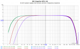
A few notes on measuring a microphone preamp (DUT)

(1) Frequency response measurements
For example, the typical frequency response of an IMG Stageline MPA-102.

MPA-102_15-ACV-mod-Version_FR_20-40-60-70dB_SR384.png

Cause: Use of a special input OP (SSM2019). Electrolytic capacitors were inserted in the gain adjustment circuit to save components (elimination of the offset voltage).

(2) Measurements of the amplifier stages
The basis for accurate measurements is a calibration of the DAC and ADC (ADC: not required for the AP) with the measured values at the input / output of the device under test: Measure with the AP or with a multimeter at ~ 70 Hz, i.e. not at mains frequency, via a cable adapter.

(3) The optimum usable output voltage (Addition to the standard measurements - Could be a new ASR standard)
Requires a multi-tone signal that best matches an average complex music signal. I use the REW signal 1/4 decade at an SR of 48 kHz.
The output voltage with the lowest value of TD+N is determined for this multi-tone signal at a fixed standard gain (microphone preamp: e.g. 40 dB). The input voltage set for the optimum output voltage is now used for further measurements: THD+N, ... (1 kHz), AES17 (41Hz 7.993kHz), CCIF (19+20kHz), ...
It should be possible to automate this process with an AP.

(4) Phantom power supply
Short-circuit current and pairing of the series resistors:
The two short-circuit currents can be measured very easily with a multimeter at the XLR input. The ratio of the two short-circuit currents [%] shows how well the series resistors are paired. A measurement of up to 0.01% should be possible.

(5) Max. Input voltage (1 kHz, dBu) at which an overload is indicated by the DUT.

(6) Measurement units
mV, dBu (dBV)
 
Top Bottom