-
Welcome to ASR. There are many reviews of audio hardware and expert members to help answer your questions. Click here to have your audio equipment measured for free!
- Forums
- Audio, Audio, Audio!
- DACs, Streamers, Servers, Players, Audio Interface
- Audio Interfaces (ADC & DAC)
You are using an out of date browser. It may not display this or other websites correctly.
You should upgrade or use an alternative browser.
You should upgrade or use an alternative browser.
How to measure EIN (Equivalent Input Noise) of an interface's Mic preamp
- Thread starter Rja4000
- Start date
Given that max input (at min gain) is spec'd at +8.7 dBu, that gives us an input sensitivity at max gain of -50.7 dBu then. That would put EIN at -123.1 dBu(A) / -122.5 dBu unweighted, or about in line with a Steinberg UR22 MkII. Not altogether terrible (I've seen much worse when dabbling in budget audio interfaces, e.g. the Steinberg UR12 is around -108 dBu), and distortion performance looks to be good, but it's pretty meh by modern standards and definitely not ideal for an SM7B. The small difference between shorted and 150 ohms alone is telling - only 0.4 dB would even suggest -121±0.5 dBu unweighted (20-20k) just in pure input voltage noise, or -120±0.5 dBu unweighted (20-20k) of EIN (*). If memory serves these EMUs were also known for that.
*) I used 150||2k = 139.5 ohms, and took the extra ~0.6 dB loss of 150 ohms into 2k into account which effectively worsens EIN. So our estimates for the direct measurement should actually be -122.5 dBu(A) / -121.9 dBu unweighted.
Not sure where the remaining discrepancy between both methods is coming from. Granted, it would probably be better to have multiple runs for the "shorted" and "150 ohm" measurements, along with a more accurate estimate of absolute levels.
Last edited:
OP
- Thread Starter
- #103
I have a pair of Revox M3500 dynamic microphones that are specified as 600 ohm.Are there mics with 50 k output impedance? Most common is 50 ohm to 200 ohm. I've seen a few at 300. I think I recall one at 600 ohms
A good microphone, very similar to it's cousin, the Beyer M201.
I personally use them as snare drum mics.
OP
- Thread Starter
- #104
Indeed.My apologies to Rja4000, maybe I've hijacked your thread for a different purpose. Didn't intend that. Maybe this belongs in the thread Amir had asking for what to test for. That turned into the Tower of Babel for mic pre testing. As a result Amir hasn't indicated any additional testing of interfaces on the preamp side.
But this is related, and I jumped on your boat as well
The method I intended to discuss in this thread is not what Amir will use, since he's using an AP, which, I hope, has no issue measuring a level around 1mV accurately.
So, for him, it's pretty straightforward, I suppose:
Set the gain at max an min values, measure input level beeded for a digital level around -10dBFS, deduct FS input level for this gain, remove source and replace by shorted plug and measure digital noise.
Deduct dynamic range and EIN under load.
Then do the same but with 3 fixed generator levels (for gain closest to 10mV, 100mV, 1V - so with a generator level 10dB below that).
A lot if manual work, but there isn't really any way to automate that, I think.
Last edited:
OP
- Thread Starter
- #105
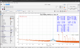
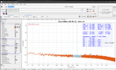
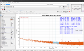
Then you'll have to measure it, I'm afraid.Ok,I did E-MU per your guide but can't find gain in specs:
View attachment 389544
Shorted
View attachment 389545
150 Ohm
View attachment 389546
Specs
What's the 0dBFS level at max gain on mic input ?
How to do that is what I'm trying to describe in my initial post.
morillon
Major Contributor
- Joined
- Apr 19, 2022
- Messages
- 1,916
- Likes
- 452
emu announces a +60 on its sister 0404 ;-)Ok.
View attachment 389555
Min gain at 0dB is -6dB RMS
View attachment 389556
Max gain at -70dB is -16.6dB RMS
View attachment 389557
min gain at -70dB is -76dB RMS
So close to 60dB?
ps for exchange...44k or 48k ?;-)))
KSTR
Major Contributor
Thinking about what I would do to get a full picture of how good a digital mic pre is wrt noise...So I'm still puzzling over the least number of things we can test to tell us what we want to know about microphone preamps practically speaking. Here is my current thinking.
A Shure SM7b is about the least sensitive microphone you run across. Most modern ribbons are more sensitive. It puts out 1.12 mV at 94 dbSPL at 1 khz. Shure suggests you need 60 db of gain minimum to make it work.
The more sensitive LDC microphones are 28 or 29 mV at 94 dbSPL at 1 khz. Let us call that a 30 to 1 ratio roughly. Which is also roughly 30 db vs an SM7b. So if we know how things work at max gain and 30 db less than max gain we have most microphones covered.
Test #1
We need to test for max input at minimum gain. You can do that with a wide range of voltages. I suggest .775 volts as that is 0 dbu. You can read it straight off the dbFS graph to see what is the max dbu input level. That and the gain range is enough for this part.
Test #2
EIN with 150 ohm resistor at max gain and 30 db less than max gain.
Test #3
EIN at max gain with a short.
(Do we need noise level at minimum gain with a short?)
Would anything be missing to tell us most of what we want to know for practical purposes?
I'm hoping to make this simple enough Amir will do this when he tests audio interfaces. Generally speaking the majority of audio interfaces use the same microphone circuit padded down for line level. Amir already tests those for distortion, frequency response and dynamic range.
So what do you guys think? Will these three tests do the job?
@Rja4000 @AnalogSteph @nanook @KSTR @restorer-john @SIY
- measure sensitivity (voltage -- in straight dBV, not deprecated and unwieldy dBu -- required to reach 0dBFS) vs gain control setting, at least at min and max settings, with known source impedance like 150R, at 1kHz
- measure source impedance correction factor, that is, sensitivity vs source impedance at a fixed gain setting, say three source impedances 15R, 150R and 1500R
- measure rms noise (in dBFS) vs gain and source impedance at selected steps, within a given bandwidth like 20Hz to 20kHz
- relate that to the known thermal noise (within the same bandwidth) of the source impedances to get a noise figure (how much worse is the DUT vs its noiseless brother).
So, the end result would be a noise figure vs sensitivity plot with source impedance as parameter.
In the application, I want to know how much worse the digital mic pre is vs the ideal, and noise figure gives me that in absolute numbers and directly human-readable format which then can also easily be used in comparisons between units.
Obviously, that would amount to dozens of measurements to be taken, so how could we best condense it?
- ditch the different source impedances, 150R is a good compromise for the real world and the (small) influence of source resistance can still be estimated
- measure sensitivity at min and max gain setting, and one reasonable intermediate setting like at 50% control knob rotation
- measure noise at min and max sensitivity and the exact same intermediate setting (hence you have to start with that setting for both measurements)
- from this calculate the final noise figure vs sensitivity table and corresponding plot, connection the three points with straight lines where basic tendencies will still be visible (like rising noise figure at very low gains)
So we're down to six simple measurements plus a bit of spreadsheeting which I would consider manageable, given that the results would be very simple and convenient to interpret. We can see the voltage range the interface can handle, and we can see how good it does handle it.
Given that one or two more intermediate gain control settings don't take any considerable additional effort I'd opt to go that way, that is we'd have 5 gain control settings, 0%, 25%, 50%, 75%, 100% where we measure sensitivity and noise.
In the application, you just read noise figure at your required sensitivity from the plot. And for a comparison of a number of units, you simply overlay their plots. No need to deal with completely non-intuitive EIN values in dBu. For those who still need that, we could add a conversion in the spreadsheet.
- Joined
- Feb 23, 2016
- Messages
- 23,575
- Likes
- 44,223
My preference would be everything in dbv. Just seems dbu is a holdover that has not had real relevance for 40 years or more.
KSTR
Major Contributor
As an addendum, some interfaces might implement soft-clipping directly in front of the ADC and never reach 0dBFS, so for these one would need to back off the sensitivity baseline to a point where a certain distortion, like 1%, is reached. Then we would have a spec for a "distortion free" range without introducing a huge penalty for this kind of circuits, not more than 3dB hopefully. Since we have to monitor distortion anyway to find the 0dBFS clipping point for regular interfaces that's no big deal.
Sokel
Master Contributor
- Joined
- Sep 8, 2021
- Messages
- 9,150
- Likes
- 9,791
Let's see if I got it.Then you'll have to measure it, I'm afraid.
What's the 0dBFS level at max gain on mic input ?
How to do that is what I'm trying to describe in my initial post.

-3dBFS is 0.953V
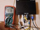
-24bBFS is 0.078V
and at near max gain just before it gets really messy looks like this:
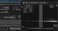
so it gets to 0.56dBFS
Did I got it right so far?
OP
- Thread Starter
- #112
Fully agree.As an addendum, some interfaces might implement soft-clipping directly in front of the ADC and never reach 0dBFS, so for these one would need to back off the sensitivity baseline to a point where a certain distortion, like 1%, is reached.
As an example, I have a Motu 828 mk 3 which saturates badly when approaching 0dBFS.
So everything should relate to that 1% or 0.1% distortion level.
(I'd rather use 1% here, since, at max gain noise will make 0.1% THD reading rather unreliable)
OP
- Thread Starter
- #113
That one is interesting and, in my method above, I'm completely ignoring it.measure source impedance correction factor, that is, sensitivity vs source impedance at a fixed gain setting, say three source impedances 15R, 150R and 1500R
Is that a fact in reality ?
How much impact could we expect ?
OP
- Thread Starter
- #114
At 1kHz, AC Voltage accuracy for your DMM is given for +/-(2.0% reading + 3 dgts)Let's see if I got it.
View attachment 389579
-3dBFS is 0.953V
View attachment 389580
-24bBFS is 0.078V
and at near max gain just before it gets really messy looks like this:
View attachment 389582
so it gets to 0.56dBFS
Did I got it right so far?
So in your case, that's 0.0078 +/- 0.0005
So your value at -24dBFS is +/- 0.58dB.
The only way to get an accurate measurement with your DMM at such voltage is to use your interface's line input, calibrate it with your Multimeter as close of 6V as possible (where your DMM accuracy will be around 0.2dB) and to use it to measure low level voltages.
KSTR
Major Contributor
Input impedance can be as low as 1kOhm and that would reduce sensitivity by 1.2dB with a 150R source, so that certainly is a factor to consider when high precision is our goal.Is that a fact in reality ?
How much impact could we expect ?
In practice, we would use a source (eg DAC) with a known output impedance -- ideally modified (upped) to give our 150R nominal -- and a known no-load voltage, and use that value rather than the measured voltage at XLR connector.
If the output and input impedance is exactly known (and hopefully not gain-dependent) we could of course simply calculate the correction from the measured value at the connector.
OP
- Thread Starter
- #116
When using the Shure A15AS attenuator, the output impedance is close enough to 150 ohm at -15dB. So I don't need to modify anything.Input impedance can be as low as 1kOhm and that would reduce sensitivity by 1.2dB with a 150R source, so that certainly is a factor to consider when high precision is our goal.
In practice, we would use a source (eg DAC) with a known output impedance -- ideally modified (upped) to give our 150R nominal -- and a known no-load voltage, and use that value rather than the measured voltage at XLR connector.
If the output and input impedance is exactly known (and hopefully not gain-dependent) we could of course simply calculate the correction from the measured value at the connector.
OK, so what we'd need is to measure input impedance as well.
In that case, I guess, we should be able to compute all values from the shorted measurement, whatever our target source impedance would be, by taking into account both the thermal noise and the level reduction.
Correct ?
KSTR
Major Contributor
I'm not quite sure what you mean.
The specs of the A15AS are not complete, we don't know which source impedance and which load impedance Shure have assumed for the attenuation specs, though actually it doesn't matter once we measure at the attenuator output.
I see no other way than comparing unloaded and loaded (by DUT) output voltage of the attenuator and derive input impedance from that, unless it's clearly stated in the DUT's specs. And then use unloaded voltage for the sensitivity calculation.
Sokel
Master Contributor
- Joined
- Sep 8, 2021
- Messages
- 9,150
- Likes
- 9,791
Calibrated with 6V range (same as the above,autoranging have put it there) and line I/O and got about the same reading (0.953 -0.951V) for the corresponding -3dB (XLR's-TRS's difference).At 1kHz, AC Voltage accuracy for your DMM is given for +/-(2.0% reading + 3 dgts)
So in your case, that's 0.0078 +/- 0.0005
So your value at -24dBFS is +/- 0.58dB.
The only way to get an accurate measurement with your DMM at such voltage is to use your interface's line input, calibrate it with your Multimeter as close of 6V as possible (where your DMM accuracy will be around 0.2dB) and to use it to measure low level voltages.
So close but not the accuracy that your test asks for (how could it be with a 100 euro interface who has traveled around the earth couple of times)
Good exercise though!
Is this -3 dB with the same setup you used for post #101? If so, the -4.1 dBFS rms @ 0 dB from the min gain measurement gives me a min gain 0 dBFS level of 0.953 V (= + 1.79 dBu) + 3 dB + 4.1 dB = +8.89 dBu. That closely agrees with the +8.7 dBu official spec.
So you current EIN estimates for the direct measurement would be -122.3 dBu(A) / -121.7 dBu unweighted (20-20k). The estimate based on noise level delta between short and 150 ohms remains unchanged at -120±0.5 dBu unweighted (20-20k).
That means we still have a ca. 1.7±0.5 dB discrepancy unaccounted for between both methods. Given the basic tools used and limited number of measurements, that's not too bad at all.
Sokel
Master Contributor
- Joined
- Sep 8, 2021
- Messages
- 9,150
- Likes
- 9,791
It's the setup I used in post #110 where the 0.953V reading corresponded to -3dBFS while for the second reading I used -6dBFS to cover the difference between the inputs.Is this -3 dB with the same setup you used for post #101? If so, the -4.1 dBFS rms @ 0 dB from the min gain measurement gives me a min gain 0 dBFS level of 0.953 V (= + 1.79 dBu) + 3 dB + 4.1 dB = +8.89 dBu. That closely agrees with the +8.7 dBu official spec.
So you current EIN estimates for the direct measurement would be -122.3 dBu(A) / -121.7 dBu unweighted (20-20k). The estimate based on noise level delta between short and 150 ohms remains unchanged at -120±0.5 dBu unweighted (20-20k).
That means we still have a ca. 1.7±0.5 dB discrepancy unaccounted for between both methods. Given the basic tools used and limited number of measurements, that's not too bad at all.
It looks like this:
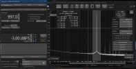
Mic In
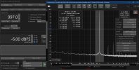
Line in
Edit: labels
Last edited:
Similar threads
- Replies
- 9
- Views
- 447
- Replies
- 1
- Views
- 607
- Replies
- 7
- Views
- 1K
- Replies
- 178
- Views
- 20K
- Replies
- 18
- Views
- 6K
