• WANTED: Happy members who like to discuss audio and other topics related to our interest. Desire to learn and share knowledge of science required. There are many reviews of audio hardware and expert members to help answer your questions. Click here to have your audio equipment measured for free!

Hivi 3.1A DIY Speaker With Sehlin Mod Review

Colonel7

Addicted to Fun and Learning
Joined
Feb 22, 2020
Messages
620
Likes
912
Location
Maryland, USA
Why would I not attribute this cleaner sound to the addition of foil capacitors added?

Reference for foil capacitor improving sound quality:
Because you hear changes to frequency not differences in capacitors as long as they are to spec. It's expectation bias. Since this is a science oriented site, the proper question is not "Why would I not", it is "Why would I?" In other words, "What is the measured mechanism or pathway to cause a change?" That would be the difference in cf to measurably change the response. @ctrl has a couple threads on capacitors and capacitor testing. Definitely stick around the site and you'll learn more and more.

That is not a reference that is just a guy talking and making up his own rules. Be wary of someone telling you the higher the cost of your tweeter the more you should pay for high-end capacitors, and that is FUD (Fear, Uncertainty, Doubt).
 

erasnick

Member
Joined
Mar 9, 2022
Messages
8
Likes
1
Because you hear changes to frequency not differences in capacitors as long as they are to spec. It's expectation bias. Since this is a science oriented site, the proper question is not "Why would I not", it is "Why would I?" In other words, "What is the measured mechanism or pathway to cause a change?" That would be the difference in cf to measurably change the response. @ctrl has a couple threads on capacitors and capacitor testing. Definitely stick around the site and you'll learn more and more.

That is not a reference that is just a guy talking and making up his own rules. Be wary of someone telling you the higher the cost of your tweeter the more you should pay for high-end capacitors, and that is FUD (Fear, Uncertainty, Doubt).
Are you saying that even if electrolytic capacitors are being used there is no measurable difference in measurable distortion to foil caps? This is a bold statement considering even my Sony speakers use foil capacitors in the tweeter circuit and this is only visible once you take the speakers apart. It seems very unlikely that Sony would choose the more expensive capacitor just to appease the very few that will dismantle their speakers. It is also true that most large speaker manufacturers do the same . So all of the engineers at all of these large companies are either ignorant or doing this just to appease the very few that dismantle the speakers and look at the crossover?
 

ROOSKIE

Major Contributor
Joined
Feb 27, 2020
Messages
1,936
Likes
3,525
Location
Minneapolis
I think the "tubby" bass will need some re-tuning of the acoustics to improve; that'll be challenging but worth it since the woofer is rated to work well down to 50 Hz. I'm going to design my own crossover circuit for these to then get a flatter response from ~50 Hz and up. The response from mods 5 & 6 (Thank you @Mudjock !) are a good starting point. I also want to take advantage of the bi-wiring so that I can bi-amp them down the line, although that may be overkill for a budget bookshelf speaker...
To be clear, it'll be my foray into owning a hi-fi system. I have plenty of experience with audio acoustic, electronics, and DSP engineering; I just haven't ever had the time or patience to have and set up my own, and I'd rather begin with something cheap (but still competent). Even so, I hardly think implementing just the crossover mod would be difficult for a beginner. I do agree that the room correction deserves its due diligence always, and that's a separate ongoing project :)

My end goal is to flatten the the on-axis response with as much bass extension as possible so that they sound as best as they can, sans-EQ. The reason I'll be re-doing the cross-over is because I plan on modding the acoustics of this speaker to achieve this goal, and that'll completely mess up the response that the crossover was intended for. I think the woofer can perform better than it is within the stock arrangement. I think it's a reasonable goal to get this woofer to extend flatly to 50 Hz reliably by tweaking the port alignment or cabinet arrangement. Of course, all of that will completely change the measurements.

If I can get the bass to extend just a tad bit lower while preserving the midrange and tweeter output and distortion, I think that's a much more solid starting point. The stock response has too much energy in the mids (kind of a "cuppy" sound to me that's most apparent in the 303's in acid house music) and clearly overemphasized highs (it's most evident to me when listening to the high frequency effects in "Sonic After-6290 Mix" or Christina Aguilera's "Genie in a Bottle") compared to hearing it on the Genelec 8341As. Amir called the HiVis "bright" in the review, but I'd go so far as to say that they're kind of "glassy" or "shouty" after hearing the un-modded version in a reference room.

What I had in mind is to flip the rear panel to have the port on the bottom with a tube extending it up to the top, and stuffing some additional damping to mask the tube from the midrange and tweeter (and perhaps absorb some of the tweeter/mid reflections and port leakage that may be causing the up-tilted stock response in the first place). I might also 3d print a different port entirely depending on how much patience I have...
Hi, re-tuning the cabinet for a tiny bit more extension will come at a cost of power handling and dynamics/compression/higher HD and IMD at lower SPL. It may be fine to drive the woofer harder if modest SPL levels are intended. I am curious why you are not satisfied with the current alignment which is quite well balanced for a 6.5" driver based system?
Getting a tiny bit more out of this woofer is a very testy gamble for gain vs loss be careful of over excursion below fB.
Bi-amping these and most speakers is near pointless and bi-wiring is even more so.
This circuit was designed with the assistance of NSF data. Frankly it will be hard for you to improve as a beginner. I am not saying don't dive in just realize crossover design is very demanding of skill, patience, knowledge and measurement gear.
Even something like 3d printing a port is a pretty big waste of time unless you love 3d printing. The HomeDepot sells all sorts of PVC plumbing for a very good price. Route the end where it meets the cabinet with at least 3/4 round over and don't use less than 2" diameter for a 6"woofer (2.5 is better)--- Or just buy a Precision port for a few bucks from PartsExpress. You can also just use cardboard tubing for testing.

If you already have enough amps to bi-amp/tri-amp, use a miniDSp or similar and create DSP based active crossovers. That is easier (though still a steep curve)as a novice and will cost you much less if you factor in all the passive parts required to be able to swap components as you test and evaluate.

Are you able to measure your work as you go, it seems from what you said not yet?

Typically electronic music and heavily produced popular electronic heavy music is a poor medium to gauge frequency response errors as there is literally zero context. Who knows which system is more accurate to the source? Nobody. Of course I understand that the Genelec reference system you have is very neutral in most ways and you can surely gauge personal preference.
Usually elevated mids are characterized with a more forward in room presence with vocals and some instrumentation more forward in the mix. A cupped hands sound is not necessarily the result of the frequency response shown in this product. I great way to mess with this is via PEQ adjustments where you can swap tuning back in forth in real time. Again a great miniDSP job.

This is a very good point, and it's part of the reason why I'll want to add a sub later on down the line to take over from that mid-bass region and below. I still think it's worth re-tuning the cabinet, because that "bump" at 100 Hz these have before any mods is characteristic of speakers with the wrong cabinet size (i.e. too small of an enclosure) and/or indicative of an improperly configured port.

Extending it down to 50 Hz would require about 3-4 dB of additional power handling, but the 60 watt nominal power rating of the woofer leaves plenty of headroom before the excursion becomes the limiting factor. Needless to say, the THD will become more of a problem before power handling, and the Loxjie A30 chokes up before driving these speakers to distortion anyway.
In its current form the driver is already excursion limited below fB and a larger cabinet will exacerbate this in multiple areas. I think you better model it in at least WINISD or similar.
Power handling specs are more or less so you know how much power the voice coil can handle before thermal compression is an issue.They have absolutely nothing to do with how the driver performs in cabinet where excursion limits are a main issue as the manufacturer has zero idea what cabinet or situation you will using the driver in.
You notions about the port tuning are not correct. The tuning is always a compromise between various factors and it is notably uncommon that all stars align.
The crossover is just not quite meeting the woofer/cabinet response ideally as most likely as that region would have been difficult for an at home designer to measure accurately.
IMHO Hivi chose a very smart cabinet size and port tuning combo given the typical use case of the speaker. Feel free to explore of course.

So I ended up putting together the speakers with the back panel upside down, and I replaced the port with a crappy bent PVC pipe pointing up with about 3 cm clearance from the port opening to the top padding. The pipe's own resonance is proving to be a problem (lol, the mids are horrible because of the extra distortion) but I'm working on printing a custom port. I'll post an STL file when I finish. I also have to figure out the best material. Putting this project on the back burner for a few weeks, though.

I also ended up using the foam that came with the kit to pad the speakers. I padded above, below, and behind the terminal box, padded that 1" space under the woofer, and padded the sides, top, and bottom. The only area that's not padded is above the crossover and that vertical cavity between the crossover and top foam.

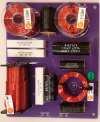
I don't have measurements, but I was able to keep the response flat from 400 Hz up to that 12.2 kHz peaking. I ended up using 7 ohms for R1 because I really wanted to tame that treble spike, and it added just a touch more flatness compared to mod 5. I used 3.5 ohms instead of 3 ohms for R2 and also used an 80 μF cap for C5 but kept L1 the same to pull down the upper mids a bit more. I'm calling it mod 5.5 because it's somewhat in-between mods 5 and 6.

The other good news is that I'm able to get these to play hilariously low. They're easily doing down to 42 Hz within 2-3 dB! It doesn't sound like a lot compared to 50 Hz, but every little bit counts in those bass frequencies. The peaking at 100 Hz is also gone, and they no longer have a tubby sound. If anything, they sound muddy/boxy/thick because of the port troubles, and I think with a better port material, they'll be perfect. With the right room (like 28 ft by 12 ft with the speaker across the shorter side), who knows - they might even go down below 40 Hz with room gain!

I wish I could measure distortion, but as far as I can tell, there is nothing additional compared to before. The only problem is the port vibrating at lower mids and adding its own distortion. When I come back to this project, I'll get a good measurement mic and post some amateur measurements.

Update: I secured the port to the board in the middle of the cabinet and added a piece of foam at that point. The vibration problem is completely solved, but I'm still going to print a more permanent/reliable rigid solution. They sound incredibly good, truly the best bang for buck at this price point.
What frequency is your (predicted)1st pipe resonance and what is the modeled port exit velocity?
Also what is the new fB? it was already tuned to about 43hrz which is quite low, tuning much lower is not advisable unless using only moderate playback levels or a sharp DSP filter below fB.

You box modeling software can predict accurately what pipe resonances you are likely to encounter, since this is a 3 way unit, ideally one would drive the resonances above the woofers pass-band and be golden.
However since you are attempting to tune lower and (this woofer plays pretty high up in this design)and thus will need a long port length in a small box you are driving the 1st strong resonance lower and the woofer will indeed pass it to the port. Liley 250-600hrz somewhere. Note that padding the box does almost nothing to any frequency below about 700-800hrz, it helps a just little from 800-1000 and is quite effective above say 1000-1200hrz. Below 100hrz it can dramatically effect port tuning and this is not always positive, it must be modeled and then ideally tested in real life.
This unit has self enclosed mids and tweeter so I actually think the padding is a fairly moot point that is more or less applied to taste for final port tuning or peace of mind but not much actual effect. It may also reduce the effective sensitivity of the woofer a little bit.

Also port velocity is a huge issue if you are using a small port diameter to get a low tuning in a pipe that fits the box. (what size is the port, diameter & length?) You may get a ton of port modulation and chuffing and it will even change the tuning as air stops flowing freely, plugging the port and effectively ruining the predicted response. You also may have mechanical driver issue and if tuned 2 low, really deep bass may over power the woofer with as little as 1watt.

You ought to also model the driver/box/port response with elevated voice coil temperatures as that changes the effective tuning and is likely more realistic vs cold modeling.

Out of curiosity what peaking are you talking about? This design does not have anechoic peaking at 100hrz. It has, depending on your view, maybe 1db of elevated response but really it aligns well with the average sensitivity of the speaker. Much of this is subjective of course.
Very rarely do folks not prefer boosted bass and 1db is not even close to enough, most will prefer more. Thankfully much of this will be handled by the room gains and speaking of that are you using any sort of PEQ on the severe room modes? If not you may be addressing room issues with this re-design vs anechoic issues.

I am surprised Amir found these tubby when many other speaker he likes have even more elevated energy here.

I totally understand you are a novice designer and so I am really trying to help(I am just a hobbyist myself) but also point out a few issue so other new users following may have a 2nd opinion here as I feel that is warranted.

Without measurements by what means are you gauging your changes?

Anyway best of luck and fun.
I have just built my Hivi 3.1A with the Perfectionist Mod option 4 however I have an amplifier that can bi-amp the speaker and the speaker does come with a binding post which is designed for this. Forgive my ignorance but if I bi-amp the speaker and run cable directly to the woofer in which case my amplifier will act as an active crossover and send only the lows to the woofer and the highs to the mid and tweeter can I leave the crossover as is and what considerations should I make if going for this? Also how would I calculate the impedance of the highs?

I'm surprised this doesn't seem to have been discussed much since it would seem to add more power to the woofer which seems to not be getting enough power in relationship to the mid and ribbon.
No, that is not how it works in terms of power delivery and unfortunately the well intended answer bellow your post is pretty far off base as well.
And for example you measure impedance, you don't calculate it.
Bi-amping these makes no real sense to implement - even for an expert audio designer with the highest skill level. Skip it entirely, that is for ultra SPL PA systems and active x-overs. The system will not sound better and as you have a steep learning curve ahead will likely just compromise this current design.
I would recommend doing further research into speaker design before moving forward here.
Have fun learning some basics before remodeling this well designed speaker.

Are you saying that even if electrolytic capacitors are being used there is no measurable difference in measurable distortion to foil caps? This is a bold statement considering even my Sony speakers use foil capacitors in the tweeter circuit and this is only visible once you take the speakers apart. It seems very unlikely that Sony would choose the more expensive capacitor just to appease the very few that will dismantle their speakers. It is also true that most large speaker manufacturers do the same . So all of the engineers at all of these large companies are either ignorant or doing this just to appease the very few that dismantle the speakers and look at the crossover?
Generally standard Dayton or Bennic capacitors are good enough.
Nobody who sells the expensive boutique stuff has even attempted a real comparison test that they have made public. Mainly just 100% subjective opinion or very poorly arranged "tests" vs actual subjective blind testing using good methods of bias and "fakery" control. Lots of money is made on the expensive x-over parts. Trust me it is good revenue for the seller.
 
Last edited:

ROOSKIE

Major Contributor
Joined
Feb 27, 2020
Messages
1,936
Likes
3,525
Location
Minneapolis
After my previous post commenting on various proposed tweaks I tested the drivers with DATS3 to get the small signal TS parameters. I did not acquire parameters with larger signals or in the enclosure.
They are different in this regard from spec but model similarly.

I estimated .63cu ft for the enclosure volume accounting for the port, brace and drivers
The tuning from Amirs testing is around 44hrz which matches the prediction with the provided port.

This system is already using a bit of an EBS type tuning and I was unable to model any changes to the port in this enclosure that will lower the f3 and f6 without greatly increasing the boosted area. Any change that deepens f3/f6 & increases 50hrz SPL also boosts the bump a bit. And in fact it actually requires a higher fB to fill in the 45-60hrz range, so a shorter port is required.
Any fB below the current 44hrz tune produces less bass and a higher f3/f6, it does however increase the output at f10. This is not a gain though as at the new f10 for the modeled lower tuning of an example 35hrz the driver can only handle 5watts of power at the 28hrz f10 before xmax is reached and this is at only 85db SPL@1meter.(so 73-78ish db in farfield)

This design should not be tuned lower in this enclosure.
If it was me I would leave it stock.
It is possible to tune it to a fB of 50hrz.
This increases bass output between 50-80hrz by about 2db for the same excursion as the stock tuning meaning you get extra SPL without added HD/IMD. I does also boost the 100hrz zone by another 0.5db or so.
Cut 2" off the port, done.

If using subwoofers I would plug the port as with this cabinet size there is no benefit to keeping the port open with subs. (& therefore no port resonances) and use a 65hrz LR4 electrical filter to give the sealed box an anechoic acoustic f6 of 80hrz and double the power handling at about 40watts -- so a pair will play 6db louder with the same distortion levels as a full-range ported stock unit.
You can also plug the port and use a 85hrz electrical LR4 high-pass to give an anechoic acoustic f6 of 90hrz. Now the speaker can handle 75watts before it just touches Xmax only at a norrow band around 100hrz and much more temporary peak power elsewhere. This allows a pair to play 10db louder than the ported full range stock pair - twice the perceived loudness. Reference level. Plus likely much more dynamic peaks and crescendos.
In both cases getting a nice blend with your sub should be fairly straight forward.
I would not use much cabinet fill in the sealed enclosure, the mids are not produced by the woofer and the cabinet is well sized for the driver so adding to much fill could affect the very optimal size it already is when sealed. You could even leave it empty of fill or put some thinner (3/4") Sonic Barrier on cab walls in case there are any resonaces but no stuffing or additional foam. https://www.parts-express.com/Sonic-Barrier-3-4-3-Layer-Damping-Material-w-PSA-18-x-24-260-530

OR for a pretty decent small floor stander
double the volume, from .63cuft to 1.3
Use the same port and cut it to 2.5"
target fB here is 45hrz

This will give approx an f1 of 40hrz(so very flatish anechoic to 40, no EBS)
F3 of 38hrz and an f6 of 35. A very good response.
Power handling is a bit less but not bad - Xmax is reached in multiple zones with 15watts of power vs 20 for the stock monitor enclosure.
It would be better to use subwoofers but in a small-medium room or larger room with modest SPL demands this tower will perform well.

also port velocity is a close call here there could be chuffing on only the most challenging tracks. A 4" diameter by 8.5" port will completely stop that and be tuned the same.

Keep in mind even a modest but well designed 8 or 10 subwoofer will outperform both the monitors and the towers so a sub is good thing.
 
Last edited:

erasnick

Member
Joined
Mar 9, 2022
Messages
8
Likes
1
Hi, re-tuning the cabinet for a tiny bit more extension will come at a cost of power handling and dynamics/compression/higher HD and IMD at lower SPL. It may be fine to drive the woofer harder if modest SPL levels are intended. I am curious why you are not satisfied with the current alignment which is quite well balanced for a 6.5" driver based system?
Getting a tiny bit more out of this woofer is a very testy gamble for gain vs loss be careful of over excursion below fB.
Bi-amping these and most speakers is near pointless and bi-wiring is even more so.
This circuit was designed with the assistance of NSF data. Frankly it will be hard for you to improve as a beginner. I am not saying don't dive in just realize crossover design is very demanding of skill, patience, knowledge and measurement gear.
Even something like 3d printing a port is a pretty big waste of time unless you love 3d printing. The HomeDepot sells all sorts of PVC plumbing for a very good price. Route the end where it meets the cabinet with at least 3/4 round over and don't use less than 2" diameter for a 6"woofer (2.5 is better)--- Or just buy a Precision port for a few bucks from PartsExpress. You can also just use cardboard tubing for testing.

If you already have enough amps to bi-amp/tri-amp, use a miniDSp or similar and create DSP based active crossovers. That is easier (though still a steep curve)as a novice and will cost you much less if you factor in all the passive parts required to be able to swap components as you test and evaluate.

Are you able to measure your work as you go, it seems from what you said not yet?

Typically electronic music and heavily produced popular electronic heavy music is a poor medium to gauge frequency response errors as there is literally zero context. Who knows which system is more accurate to the source? Nobody. Of course I understand that the Genelec reference system you have is very neutral in most ways and you can surely gauge personal preference.
Usually elevated mids are characterized with a more forward in room presence with vocals and some instrumentation more forward in the mix. A cupped hands sound is not necessarily the result of the frequency response shown in this product. I great way to mess with this is via PEQ adjustments where you can swap tuning back in forth in real time. Again a great miniDSP job.


In its current form the driver is already excursion limited below fB and a larger cabinet will exacerbate this in multiple areas. I think you better model it in at least WINISD or similar.
Power handling specs are more or less so you know how much power the voice coil can handle before thermal compression is an issue.They have absolutely nothing to do with how the driver performs in cabinet where excursion limits are a main issue as the manufacturer has zero idea what cabinet or situation you will using the driver in.
You notions about the port tuning are not correct. The tuning is always a compromise between various factors and it is notably uncommon that all stars align.
The crossover is just not quite meeting the woofer/cabinet response ideally as most likely as that region would have been difficult for an at home designer to measure accurately.
IMHO Hivi chose a very smart cabinet size and port tuning combo given the typical use case of the speaker. Feel free to explore of course.


What frequency is your (predicted)1st pipe resonance and what is the modeled port exit velocity?
Also what is the new fB? it was already tuned to about 43hrz which is quite low, tuning much lower is not advisable unless using only moderate playback levels or a sharp DSP filter below fB.

You box modeling software can predict accurately what pipe resonances you are likely to encounter, since this is a 3 way unit, ideally one would drive the resonances above the woofers pass-band and be golden.
However since you are attempting to tune lower and (this woofer plays pretty high up in this design)and thus will need a long port length in a small box you are driving the 1st strong resonance lower and the woofer will indeed pass it to the port. Liley 250-600hrz somewhere. Note that padding the box does almost nothing to any frequency below about 700-800hrz, it helps a just little from 800-1000 and is quite effective above say 1000-1200hrz. Below 100hrz it can dramatically effect port tuning and this is not always positive, it must be modeled and then ideally tested in real life.
This unit has self enclosed mids and tweeter so I actually think the padding is a fairly moot point that is more or less applied to taste for final port tuning or peace of mind but not much actual effect. It may also reduce the effective sensitivity of the woofer a little bit.

Also port velocity is a huge issue if you are using a small port diameter to get a low tuning in a pipe that fits the box. (what size is the port, diameter & length?) You may get a ton of port modulation and chuffing and it will even change the tuning as air stops flowing freely, plugging the port and effectively ruining the predicted response. You also may have mechanical driver issue and if tuned 2 low, really deep bass may over power the woofer with as little as 1watt.

You ought to also model the driver/box/port response with elevated voice coil temperatures as that changes the effective tuning and is likely more realistic vs cold modeling.

Out of curiosity what peaking are you talking about? This design does not have anechoic peaking at 100hrz. It has, depending on your view, maybe 1db of elevated response but really it aligns well with the average sensitivity of the speaker. Much of this is subjective of course.
Very rarely do folks not prefer boosted bass and 1db is not even close to enough, most will prefer more. Thankfully much of this will be handled by the room gains and speaking of that are you using any sort of PEQ on the severe room modes? If not you may be addressing room issues with this re-design vs anechoic issues.

I am surprised Amir found these tubby when many other speaker he likes have even more elevated energy here.

I totally understand you are a novice designer and so I am really trying to help(I am just a hobbyist myself) but also point out a few issue so other new users following may have a 2nd opinion here as I feel that is warranted.

Without measurements by what means are you gauging your changes?

Anyway best of luck and fun.

No, that is not how it works in terms of power delivery and unfortunately the well intended answer bellow your post is pretty far off base as well.
And for example you measure impedance, you don't calculate it.
Bi-amping these makes no real sense to implement - even for an expert audio designer with the highest skill level. Skip it entirely, that is for ultra SPL PA systems and active x-overs. The system will not sound better and as you have a steep learning curve ahead will likely just compromise this current design.
I would recommend doing further research into speaker design before moving forward here.
Have fun learning some basics before remodeling this well designed speaker.


Generally standard Dayton or Bennic capacitors are good enough.
Nobody who sells the expensive boutique stuff has even attempted a real comparison test that they have made public. Mainly just 100% subjective opinion or very poorly arranged "tests" vs actual subjective blind testing using good methods of bias and "fakery" control. Lots of money is made on the expensive x-over parts. Trust me it is good revenue for the seller.
Your response is not relevant to my response. I was debating the following statement "Because you hear changes to frequency not differences in capacitors as long as they are to spec. It's expectation bias". I think there is an overwhelming evidence to the contrary. Electrolytic vs foils capacitors should not even really be a debatable topic, nor should iron-core vs air-core inductors when talking about passive crossovers. I have built, experimented, and blind tested enough at this point to know that someone trying to debate this simple fact is either a troll or arguing from ignorance.
 

ROOSKIE

Major Contributor
Joined
Feb 27, 2020
Messages
1,936
Likes
3,525
Location
Minneapolis
Your response is not relevant to my response. I was debating the following statement "Because you hear changes to frequency not differences in capacitors as long as they are to spec. It's expectation bias". I think there is an overwhelming evidence to the contrary. Electrolytic vs foils capacitors should not even really be a debatable topic, nor should iron-core vs air-core inductors when talking about passive crossovers. I have built, experimented, and blind tested enough at this point to know that someone trying to debate this simple fact is either a troll or arguing from ignorance.
The problem is there is little evidence to support your claims only you thinking there is. If there actually was you will be linking like mad to many tests reports and published literature that is conclusive and well informed & not only anecdotal subjective reporting and certainly not from a manufacturer who benefits greatly from boutique caps selling.
That said I myself was not promoting electrolyte capacitors per say or iron core inductors but rather poo-pooing boutique crap. It is BS. Not one single blind test done by any of the manufacturers or advocates like GR research. Put that in your tube connector.
If you have done proper blind testing of $80 fancy foil vs a $10 Dayton Poly Cap do a proper write up here and get the party started. It would be appreciated. That said until then I am saving $70 per cap and am pretty certain that is good idea. (though again, hey if you can show your work, let's go into that rabbit hole)

Plus in 2022 spending $600 on xover parts for a 2way is absurd. For equal money just make an active speaker with DSP, zero degradation from any passive parts much more control and accuracy/flexibility.
 
Last edited:

ROOSKIE

Major Contributor
Joined
Feb 27, 2020
Messages
1,936
Likes
3,525
Location
Minneapolis

maltux

Member
Joined
Jan 4, 2020
Messages
92
Likes
150
Location
Buffalo, NY
One more post here from me.
Public Service style this is 10% off at Amazon right now if you "clip" the coupon.
$270 vs $300
get on a set now

Wish I would have seen this link yesterday when I bought the kit for my wife to give me on my birthday. I bought the upgrade (mod 4) crossover parts from parts express as well. I built the 2.1 Hiv DIY two years ago and am very fond of them; currently my primary music system speaker. I used veneer on the 2.1's and am not sure how I will finish the new kit.
 

Cipriano

Member
Joined
Apr 28, 2022
Messages
5
Likes
0
Hello, I am an electronics novice and I just purchased a Swan 3.1a kit. Does someone mind pointing me in the direction of the best resistors for adding to the tweeter and mid? It will be fix #1 so I'll need two 10 ohm and two 5.6 ohm resistors. Parts Express has three options: Mills non-inductive, Dayton fireproof ceramic, and the Dayton audio grade ones rated at 10 watts. Which of these would be the correct type, or would you recommend something else entirely? Thanks!
 

ROOSKIE

Major Contributor
Joined
Feb 27, 2020
Messages
1,936
Likes
3,525
Location
Minneapolis
Hello, I am an electronics novice and I just purchased a Swan 3.1a kit. Does someone mind pointing me in the direction of the best resistors for adding to the tweeter and mid? It will be fix #1 so I'll need two 10 ohm and two 5.6 ohm resistors. Parts Express has three options: Mills non-inductive, Dayton fireproof ceramic, and the Dayton audio grade ones rated at 10 watts. Which of these would be the correct type, or would you recommend something else entirely? Thanks!
It is highly unlikely there is any SQ benefit, all of these will likely work perfectly and I would usually just use the standard sand cast cheapo ones.
That said some others swear the Mills resistors provide a sonic benefit, so if you really are concerned you may be missing out, use those.
Far more benefit would likely come from using the later mods that were created after the Klipple testing.
 

maltux

Member
Joined
Jan 4, 2020
Messages
92
Likes
150
Location
Buffalo, NY
I just finished mine. Here are a few screen shots. I did modification 4 using the provided circuit board.
 

Attachments

  • Perfectionist crossover on Hivi DIY 3.1.png
    Perfectionist crossover on Hivi DIY 3.1.png
    1.2 MB · Views: 176
  • Screen Shot 2022-08-31 at 4.54.06 PM.png
    Screen Shot 2022-08-31 at 4.54.06 PM.png
    204.5 KB · Views: 171

Billy Budapest

Major Contributor
Forum Donor
Joined
Oct 11, 2019
Messages
1,858
Likes
2,788
The Mills wirewound and Dayton ceramic would both be good choices—resistors in this application tend to get hot and these two so-called “sand cast” resistors are best suited for the job.
 

Cipriano

Member
Joined
Apr 28, 2022
Messages
5
Likes
0
The "sand cast" dayton are the ones labeled audio grade with rectangular white boxes, correct?
 

ROOSKIE

Major Contributor
Joined
Feb 27, 2020
Messages
1,936
Likes
3,525
Location
Minneapolis
The "sand cast" dayton are the ones labeled audio grade with rectangular white boxes, correct?
Yes, sorry I forgot "sand cast" doesn't mean much when you are new. The Mills are also ceramic inside(so also could be called, sand cast, but are usually just called by name, Mills) they come with some modest additional designs traits but they cost more to make and sell and do the same job. Use the cheap ones IMHO
 
Last edited:

Cipriano

Member
Joined
Apr 28, 2022
Messages
5
Likes
0
Alright, I got one speaker up and running. I hate those hex-head screws they provide! The hardest part was strapping the 10 ohm resistor across the terminals on the midrange as the terminals are on opposite sides of the midranges thick barrel. I had to find some donor resistors, snip off some leads and daisy chain them to make the leads long enough.

I think I overstuffed them also. In a bass reflex design, should you leave the area in front of the port clear of stuffing? When I look into the port hole all I see is polyfill. I didn't use the shipping foam as some do.

Thanks
 

Mudjock

Member
Audio Company
Joined
Mar 5, 2020
Messages
97
Likes
180
Generally, for a bass reflex design one would line the walls with insulation - maybe a couple of inches thick, but not stuff the enclosure. The area in front of the port should be clear of stuffing unless the design specifically calls for that. The DIY 3.1 should not have stuffing in front of the port.
 

stallhagen

New Member
Joined
Sep 11, 2022
Messages
1
Likes
0
Hi folks,
I know this is a Hivi 3.1 thread, but I couldn't find any recent ones related to 2.2A so I'm hoping to get some answers here.

I've had the 2.2a's for about 3 years now and I love them, but after a recent move one of the woofers is not working any more. Tweeter works normally but no sound from woofer. I opened the cabinet, disconnected the woofer, and tested the Resistance with a multimeter, which was 6.5 ohm. It's not that far from the rated 8ohm so seems ok. I tested the other connections on the PCB and they all seemed fine. Capacitors were harder to test, but I took them out, drained them and tested the resistance and it seemed to move/charge so not sure. It's not the cable or my receiver, I've cross-tested those.

Any ideas/feedback would be greatly appreciated. Thanks
 
Top Bottom