• WANTED: Happy members who like to discuss audio and other topics related to our interest. Desire to learn and share knowledge of science required. There are many reviews of audio hardware and expert members to help answer your questions. Click here to have your audio equipment measured for free!

Fun with vinyl measurements

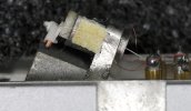
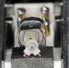
Putting the question in this thread instead. Those of you that have Nagaokas MP-500 with a boron solid cantilever: Is it possible to get some measurements of the boron cantilever length? Just that portion that is visible as the boron rod. The JICO boron rod is just below 4 mm long, I would guess 3.8 mm. Obray specifies their boron cantilevers as 6±0.2 mm.


View attachment 408601
 
They measured it this way:
Audio technica tonearm, Victor turntable.
Tonearm lowered by hand, no arm lowering lever ;)

Mea.jpg


Machines for producing silencers.

Damper.jpg
 
Last edited:
90% of those who offer MC cartridge repair do not measure the cartridges they repair. :)
Almost none of them have original high frequency attenuators.
The most common repair involves gluing a new bracket onto the old bracket, suspension, etc....
 
A dozen or so more tests and you will know what fits and what doesn't, and how to do it correctly. Rome wasn't built in a day ;)

1. Note that the needles you bought should work with a pressure of 2 grams, and cartridges with T4P mounting have a recommended pressure of 1.25 grams

2. The compliance is regulated here by a string - a steel wire that is inside, - the pressure is related to the compliance.

3. There is a high-frequency attenuator at the front, it is a very important element!

4. Meters will come in handy, resistance and inductance, capacitance

5. Of course, you always have to measure, this program is great for that

6. Crosstalk came out very well, the tip was set evenly :)


View attachment 408631


View attachment 408632
AT no longer uses steel wire in MM cartridges. It seems to me that these photos are more than 30 years old :)
 
AT no longer uses steel wire in MM cartridges. It seems to me that these photos are more than 30 years old :)
Yes, these photos are almost 40 years old
Of course there is a steel wire inside, a string, this is the suspension of the bracket. Otherwise it wouldn't work.......
Please remove the high frequency damper - it's the black elastic element and check :)

a2.jpg
 
AT no longer uses steel wire in MM cartridges. It seems to me that these photos are more than 30 years old :)

I haven't looked there in a long time. :) I checked the new needle.

You're right, the bracket suspension is on a flexible plastic element.

In older needles, this element was metal.

I used high temperature and the suspension melted.


Plastic.jpg
 
A dozen or so more tests and you will know what fits and what doesn't, and how to do it correctly. Rome wasn't built in a day ;)

1. Note that the needles you bought should work with a pressure of 2 grams, and cartridges with T4P mounting have a recommended pressure of 1.25 grams

2. The compliance is regulated here by a string - a steel wire that is inside, - the pressure is related to the compliance.

3. There is a high-frequency attenuator at the front, it is a very important element!

4. Meters will come in handy, resistance and inductance, capacitance

5. Of course, you always have to measure, this program is great for that

6. Crosstalk came out very well, the tip was set evenly :)


View attachment 408631


View attachment 408632
all of these tests were done with the stylus tracking at 2 grams. all bodies were measured. capacitance of leads were measured. i discussed compressing the damper. ;)
 
In this model, which I once had, the suspension of the bracket was on a metal rod.
There was a possibility of adjusting the compliance, i.e. the tension of the suspension of the bracket.
The cartridge was very interesting, it had laminated coils, and, also inside, an additional metal cover for the coils.

It is possible, because I do not know, that in higher models the suspension is made on a metal rod, and in lower models this element is plastic?
Currently, in lower models the bracket is mounted to the plastic frame using a cheaper method, using a pin, and in higher models the bracket is attached with a screw-in screw.


Clipboard_11-22-2024_02.jpg


Clipboard_11-22-2024_01.jpg
 
Last edited:
What do they use now?
Something similar to a fishing line, black in color. The metal string is easily deformed, sometimes it falls out of the brass sleeve.
_SAM8169.JPG_SAM8174.JPG
Here are the consequences of the steel string slipping out of the brass sleeve, dead coils, wire breakage from the coil.
 
Last edited:
Something similar to a fishing line, black in color. The metal string is easily deformed, sometimes it falls out of the brass sleeve.
View attachment 408817View attachment 408818
Here are the consequences of the steel string slipping out of the brass sleeve, dead coils, wire breakage from the coil.
This is an MC type cartridge.
The question concerns needles for MM type cartridges
Currently, for example in the VM-95ML/VM-95SH cartridge needle model, I checked, the entire suspension is one whole, it is made entirely of plastic.
This is a completely different construction than in the case of older needles.
I posted these photos as one of the assumptions for which AT replaced the steel string with plastic.
 
Played with the SP-02 demonstration record today. Sadly it's all music with no technical tracks, but we can make do.

IMG_0564.JPG


Their torture track is the first band, where "The musical signal in Band-l is cutted under variable pitch and variable depth of the cutter. It can be used for the dynamic wow/flutter comparison. The cutter is operated 5 second interval with variable pitch/depth control." Side A is cut with a Lyrec motor, and side B is cut with an SP-02.

The spectrum of A1 and B1 respectively, with the section I analyzed marked. Third picture is a zoomed-in comparison of the marked sections:

Technics Neumann SP-02 Demo A1 Spectra.png


Technics Neumann SP-02 Demo B1 Spectra.png


Techncis Neumann SP-02 Demo Disc Spectra.png


The last is the actual content that was analyzed. I used the instantaneous frequency detection method from the polar plot script, and plotted that section from both sides. This is heavily filtered as there's a lot of noise - it's real people playing real instruments.

Technics Neumann SP-02 Demonstration Record.png


**EDIT** Link to files: https://www.dropbox.com/scl/fi/no1o...emo1.zip?rlkey=dwcngnjtt6xl60kaq23t7ldso&dl=0
 
Last edited:
Back
Top Bottom