• Welcome to ASR. There are many reviews of audio hardware and expert members to help answer your questions. Click here to have your audio equipment measured for free!

Fosi Audio LC30 Speaker/Amp Switcher & Meter

Rate this speaker/amp switcher and meter:

  • 1. Poor (headless panther)

    Votes: 26 17.9%
  • 2. Not terrible (postman panther)

    Votes: 25 17.2%
  • 3. Fine (happy panther)

    Votes: 62 42.8%
  • 4. Great (golfing panther)

    Votes: 32 22.1%

  • Total voters
    145
Just being kind of curious about the conclusion of the test. How about the performance?
Well as a VU meter, it's not accurate, but as a visual of dancing needles it does the job fine there.

As a speaker switch/selector, you can see Amir's testing results and same shows the device is fairly clean in relation to noise and minimal distortion added.


JSmith
 
Well as a VU meter, it's not accurate, but as a visual of dancing needles it does the job fine there.

As a speaker switch/selector, you can see Amir's testing results and same shows the device is fairly clean in relation to noise and minimal distortion added.


JSmith
Got it. Thanks for your kindly explanation.
 
Welcome to ASR.

Using a resistor network to pad down the amplifier output will significantly alter the output impedance of the amplifier as seen by the speakers, which can significantly affect the frequency response of the speaker/amp combination. That will invalidate your speaker comparison test.

It's much better adjust the signal levels at the input of the speaker amplifier(s).
OK good point. But it makes things even more difficult. This would require an "integrated" device that can simultaneously and instantaneously change the output to speakers and also adjust the signal levels at the input of amplfiier (here I assume only 1 amplifier).

Looks like proper testing/comparison is not that easy.
 
This is a review and measurements of the Fosi Audio LC30 Speaker and amplifier switcher plus "power" meters. It was sent to me by the company and costs US $150.
View attachment 396215
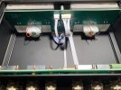
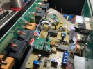
As you see, this is a gorgeous unit, sporting prettier meters than a lot of what vintage audio gear used to have. I always considered a meter with flat line markings as cooler. :) Both the case and switchgear have a higher quality feel than what I expected. Hitting the selector buttons causes reassuring relay clicks internally. The on/off switch doubles as 3 steps of back light plus off. The gain control has wide range and seems to work better than some of the others I have tested.

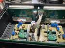
The unit is powered by a USB-C connector:
View attachment 396216
You have a choice of two amplifiers and two speakers.

I spent a few minutes to see if the meters show the correct power wattage and they are hopelessly wrong. I would calibrate my amplifier output to a wattage displayed on the meter but when I changed it, the amount of change on the display was wildly different. Contacted Fosi to see if there is an impedance they calibrated to and the answer was: it is not calibrated to anything. It is just for fun.

And fun it is to watch those beautiful meters move. Sensitivity seems good with decent speed.

Fosi Audio LC-30 Measurements
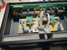
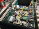
I spent two days trying to measure the impact of LC30 on amplifier performance. I used the Purifi reference design amp to drive the LC30. As I had predicted and feared, the Purifi performance is so good that even slightest change in the impedance of its speaker connection causes third harmonic distortion (seen below). I bought more connectors and built new short speaker cables. I tightened and tightened the connections. Swapped wires and ran a bunch of experiments. But at the end, the impact could not be avoided:
View attachment 396218

There is a dashed blue line which shows the performance of Purifi amp direct. The red mark is the impact of LC30 if you use it as a switcher by routing the speaker output through it. The so called "VCR" (Voltage Coefficient Resistance) shows up more and more as power increases due to resistance variations based on voltage applied. I tried the Topping B100 with same effect. Then I realized that you don't need to use the unit as a switcher. My speaker connectors have a rear banana jack (i.e. they can pass the signal through) so I connected that to LC30. With speaker cables now remaining on the amplifier, we get the performance in green that is overlaid on dashed blue, indicating no impact.

Notice how the noise level is not impacted at all despite the extra cables even in switched mode (the graph before 10 watts). So the issue is only distortion. I am using locking banana connectors above and still registered an impact. If you use anything else, expect a bigger hit. In one case, the connector was a bit less tight and I registered massive distortion and half as much power! So if you are going to use it as a switcher, with a high performance amp, you really need to go the extra mile to get an extra tight connection all around (connector and wire to connector).

Now, if you don't have such a high performance amplifier, then the issue is much less significant to the point of not mattering. Here is LC30 as a switcher in the output of Fosi's own ZA3 amplifier:
View attachment 396220
As you see there is no performance hit even though I have all the extra cables and connectors. Also, some amplifiers will be less impacted by extra connections and cables.

For kicks, I also ran a crosstalk test with Purifi using LC-30 as a switcher:
View attachment 396221

But note that I did not make an attempt to separate my jumper speaker cables so some of this may be due to that.

Given the passive way you can connect the LC30, i.e., not using it as a switcher, I don't see a reason to run other tests.

Conclusions
The LC30 from Fosi brings us a high quality fun meters with switching ability. If you just want dancing meters, I suggest tapping from the amplifier speaker binging to LC30 and not routing your signal through it. That's the way I would use it. If you are going to use it as an AB switch, you should invest in proper set of short cables. Be careful for any AB quality tests as there can be an audible impact here if utmost attention is not paid to wiring (no fault of this unit but in general).

And oh, don't try to use it as a power meter. It is not for that.

The build quality is excellent and the unit is one of the most beautiful of its kind.

I am going to recommend the Fosi LC30 meter and speaker/amplifier switcher for fun factor.
------------
As always, questions, comments, recommendations, etc. are welcome.

Any donations are much appreciated using: https://www.audiosciencereview.com/forum/index.php?threads/how-to-support-audio-science-review.8150/
Apologies in advance if I'm exhibiting my ignorance but I just cannot understand these two sentences:

"My speaker connectors have a rear banana jack (i.e. they can pass the signal through) so I connected that to LC30. With speaker cables now remaining on the amplifier, we get the performance in green that is overlaid on dashed blue, indicating no impact."

I've tried drawing a schematic, my logic tells me that you're connecting the speakers in parallel to the LC30, Wouldn't this result in impedance problems? As far as I can tell, you have to connect the LC30 in series with the speaker or the LC30 won't function. I'd like to try this but I cannot visualise how it would work. I guess you'd use a Y-splitter at the amplifier speaker terminals and another at the speaker terminals but adding so many connections seems to me like defeating the purpose. I'm sure I'm missing something obvious...
 
Last edited:
Apologies in advance if I'm exhibiting my ignorance but I just cannot understand these two sentences:

"My speaker connectors have a rear banana jack (i.e. they can pass the signal through) so I connected that to LC30. With speaker cables now remaining on the amplifier, we get the performance in green that is overlaid on dashed blue, indicating no impact."

I've tried drawing a schematic, my logic tells me that you're connecting the speakers in parallel to the LC30, Wouldn't this result in impedance problems? As far as I can tell, you have to connect the LC30 in series with the speaker or the LC30 won't function. I'd like to try this but I cannot visualise how it would work. I guess you'd use a Y-splitter at the amplifier speaker terminals and another at the speaker terminals but adding so many connections seems to me like defeating the purpose. I'm sure I'm missing something obvious...
you are right - in this setup it is defeating the purpose of beeing a switchbox and working solely as a meter, as far as I understand the sentence :)
 
Hi everyone, thoughts about using this Fosi unit responsibly with a Hypex NC502MP 2 channel? I know that's way over the max wattage for this unit, however, if I am not turning it up too loud, you think I'll have any issues? The Hypex is connected to 2 CSS 1TDX Triton's (8 ohms).

Also, I am fairly new to this stuff, is Amir saying that I need to have as short of speaker cables as possible? so the quality of the signal is not impacted? That's what I took from reading the review. I also would consider just tapping into the speaker posts of the Hypex amp and not running it through the Fosi, because I only want this unit for aesthetics, and to not catch fire.

Thanks in advance!
 
Last edited:
An interesting and useful lesson regarding quality of speaker connections when using high quality, high power amplifiers!
Just installed the FOSI LC30.
As my cables/connectors were a bit old, I took advantage by replacing them with brand new ones.
Purchased 32 banana plugs and a total of 20m of AWG 12 ...and a permanent marker ;-)
Had fun !
@ Fosi : different color LEDs, please.
 
Check this out from BobWire. I'm planning to get one to switch 2 amps to a single set of speakers.

Update.

I did purchase the BobWire 2 amplifier switch. Works flawlessly. Switching 2 amplifiers into my L/R Revel F226BE speakers. The first amp is a Benchmark AHB2 rated at 100W @ 8 Ohms which I use for stereo music. The second amp is the L/R output from a 400W @ 8 ohms Class D amp that's part of my 11.3.4 home theater setup. I do not notice any impact to sound quality. Using 10AWG speaker cables and according to BobWire the resistance of the switch is equivalent to 1 foot of 12AWG copper wire. If you need high power compatibility and don't care about meters then this is a good solution. Link to BobWire below.

 
I bought the LC30 two weeks ago. In my eyes mechanical and optical a very well done device but for me it has two issues:

1. it does not self power on if 5V comes up via USB. Would like to see a jumper inside where this could be configured.
2. the display is uncalibrated. Nearly no movement at low levels and the meter swings much too fast.

I decided to develop an add on prototype PCB which I mounted into the box. There is much space inside so my additional prototype PCB nicely fits in there. It uses two AD8310 devices (used it as I never worked with it before and was curious) to create a real logarithmic output. Also I added some other components to be able to exactly calibrate the meters.

As I‘m not able to solder the tiny AD8310 I bought two of these PCBs, and mounted them on top of my breadboard. I had to modify them a bit to work with audio frequencies but this was quite straight forward.

With two potentiometers I’m now able to calibrate the 0dB and the -40dB levels at 1000Hz. After calibration the levels in between also fit. Only drawback is that the scale of the meters above 0dB is not logarithmic. So the values shown above 0dB are wrong. A damping resistor across the meter establishes critical damping so I get only a very small overshoot from pulses.
I‘m very happy now with this solution :)

I also integrated a NE555 and a small DIL Relais that simulates pressing the power button after 5V from USB comes up.

If someone is interested I offer to draw the schematics and publish it here. I also made some fotos during my work that I’m also willing to share. Maybe someone with skills in PCB layouting and producing will kick in and build a circuit board equipped with components so others also can upgrade their unit.

Best DrCWO
 
A purist would argue that the speaker impedance is not linear...
The calibration looks valid only for 1000Hz in your speakers. But it's better than nothing.
Your power switch interests me : can you give more info ?
Regards,
 
A purist would argue that the speaker impedance is not linear...
The calibration looks valid only for 1000Hz in your speakers. But it's better than nothing.
Your power switch interests me : can you give more info ?
I calibrated in dB not W. So voltage only was important. For me the benefit is that the meters move logarithmic so I can set the knob at the device once for all volumes and have moving pointers no matter how loud I listen.

I will do the schematics tomorrow and post it here.

Best DrCWO
 
Here is the schematics

EDIT:
I discovered a small mistake in the Schematics:
A Diode N4148 has to be inserted between the output of the AD8310 and the 470 Ohm resistor ;)
 

Attachments

  • IMG_0704.JPEG
    IMG_0704.JPEG
    260.8 KB · Views: 59
Last edited:
And here some Fotos of my implementation.

EDIT:
I like to add some hints regarding calibration of the unit.
  1. Apply a 1kHz signal to the input from an amplifier to the left channel ONLY.
  2. Connect a cable from the left channel input to the right channel input.
  3. Connect a Voltmeter to the output of the A8310 left channel.
  4. Adjust the potentiometer at the front of the LC30 to get 2,57V at the voltmeter
  5. Adjust P1L till the meter shows 0dB at the left VU meter.
  6. Now change Volume to -40 at the amplifier.
  7. Adjust P2L till the meter shows -40dB
  8. Change Volume back to 0dB at the Amplifier
  9. Repeat from step 5. until both readings are correct.
  10. Now perform the same procedure with P1R and P2R and the right VU meter.
 

Attachments

  • IMG_0691.JPEG
    IMG_0691.JPEG
    52.7 KB · Views: 67
  • IMG_0693.JPEG
    IMG_0693.JPEG
    247.8 KB · Views: 73
  • IMG_0694.JPEG
    IMG_0694.JPEG
    258.5 KB · Views: 69
  • IMG_0695.JPEG
    IMG_0695.JPEG
    286.1 KB · Views: 84
  • IMG_0696.JPEG
    IMG_0696.JPEG
    285 KB · Views: 84
  • IMG_0699.JPEG
    IMG_0699.JPEG
    268.9 KB · Views: 57
  • IMG_0698.JPEG
    IMG_0698.JPEG
    284.2 KB · Views: 74
  • IMG_0700.JPEG
    IMG_0700.JPEG
    246.2 KB · Views: 61
  • IMG_0701.JPEG
    IMG_0701.JPEG
    240.9 KB · Views: 63
  • IMG_0702.JPEG
    IMG_0702.JPEG
    282 KB · Views: 64
Last edited:
Your power switch interests me : can you give more info ?
In the lower part of the circuit diagram, you can see the NE555 chip and its wiring. It controls a relay whose outputs are connected to the power switch contacts on the front panel via two thin yellow wires.

To solder these wires there, you have to disassemble the entire device. You need to use very thin wires so they don't interfere with assembly. You can see the wires in my photos.

Best DrCWO
 
I want this, but including this into a digital system is not trivial…
if you have active speakers you have no chance of including the LC-30 - maybe you should aim fior some kind of line level meter as this wonderful digital meter

If the formfactor is not you - then there is a lot of other alternatives out there
 

Attachments

  • tc clarity.JPG
    tc clarity.JPG
    47.1 KB · Views: 16
I want this, but including this into a digital system is not trivial…
 

Attachments

  • Am au.JPG
    Am au.JPG
    59.3 KB · Views: 14
Even if calibrated for better accuracy, I think it is sort of anecdotal because it isn't all that useful to see "Watts". It would be useful to see just voltage and current. "Watts" is somewhat useful if measured on the power input side though.
I would like to ask in what scenarios can voltage or current be displayed?
 
Back
Top Bottom