• WANTED: Happy members who like to discuss audio and other topics related to our interest. Desire to learn and share knowledge of science required. There are many reviews of audio hardware and expert members to help answer your questions. Click here to have your audio equipment measured for free!

eRIAA phono preamp

depo196

Member
Joined
Nov 27, 2023
Messages
14
Likes
6
Location
Dresden, Deutschland
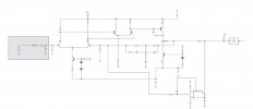
Let me inrtodce transformer free Phonograph Preamplifier for MM and MC cartridges based on the most modern component and design. Just admire please
6 main advantages:
1. Constant loop gain for no THD both @ LF and HF,
2. No coupling capacitors at all, MC-like sound with MM cartridge thanks to
3. aperiodic non-resonant HF correction with lowest input capacitance.
Thanks fo that, the unwanted resonance of the input circuit is shifted far into the ultrasound region and does not manifest itself in the audio range, and the input resistor R1 can be increased to 150 kOhm, thus forming a "passive cooling", which reduces the input noise current in SQRT (150 kOhm / 47 kOhm) = 1.78 times compared to typical Rin = 47 kOhm.
4. At the front end uses a matched pair of Dual, ultra-low noise, low-gate-current audio N-channel JFET - the latest JFE2140 from Texas Instrument. It's allow to achieve a record IEC-A weighted signal-to-noise ratio of 85 dBA relative to a standard 5 mV@1 kHz input level with an attached 0.5 H+ MM head equivalent. 1 kOhm
5. and THD less, then 0.00006% with fantastic overload capacity (64 mV@1 kHz < 0.0007%).
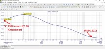
6. The frequency response exactly corresponds to the Enahanced RIAA not with three, as usual, but with five time constants, in addition to 75 + 318 + 3180 µs, a Neumann pole compensator and a rumble-reducing 7950 µs - IEC 98 Amendment are also implemented.

MM
Frequency range: 1 Hz - 45 kHz
Ku at 1 kHz: 49 dB
rated output voltage: 1.4V
signal to noise ratio: >85 dBA
THD for input signal: 5mV@1kHz: <0.00006%

MC
Frequency range: 1 Hz - 45 kHz
Ku at 1 kHz: 68 dB
rated output voltage: 1.4V
signal to noise ratio: >73.9 dBA
THD for input signal: 0.4 mV@1 kHz: <0.0004%
 

Attachments

  • 1.jpg
    1.jpg
    143.9 KB · Views: 244
  • 3.jpg
    3.jpg
    90.7 KB · Views: 238
  • 5.jpg
    5.jpg
    25.3 KB · Views: 241
Hello,

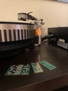
This is a fully assembled, configured and tested electronic board, ready for installation inside a player, with the shortest possible wires. Price 180 Euro.
There is also a toroidal power transformer with a rectifier and a supply voltage stabilizer - +-15V. Price 20 Euro.
See the picture please

IMG_7294.jpg
2.jpg
 
Who assembled and soldered this pcb?
That's not according to IPC!
This is an experimental solution. I soldered it. I hope it will get the deserved rating and will be produced at the factory, but then the price will be different
 
Who assembled and soldered this pcb?
That's not according to IPC!
I agree. I am PACE Certified for through hole and SMD PCBs and looking at that PCB solder makes me think of somebody that has poor eye hand coordination and bad soldering skills. :facepalm:
 
This is an experimental solution. I soldered it. I hope it will get the deserved rating and will be produced at the factory, but then the price will be different
Ahhh you are new to soldering. Try a little little higher iron temp and use liquid flux for nice shiny solder that does not have inconsistencies.
 
Ahhh you are new to soldering. Try a little little higher iron temp and use liquid flux for nice shiny solder that does not have inconsistencies.
That's right. I'm an acoustic engineer, not a soldering station assembler. My job is to develop. But this solution is the work of my acoustics department supervisor, Nikolai Sukhov, a brilliant circuit designer, the author of bold, elegant and useful solutions for audio.
 
That's right. I'm an acoustic engineer, not a soldering station assembler. My job is to develop. But this solution is the work of my acoustics department supervisor, Nikolai Sukhov, a brilliant circuit designer, the author of bold, elegant and useful solutions for audio.
IC. Maybe he was trying to minimize the high temp of the iron and was placing the components and then quickly tacking them in place in a manner that reduced the soldering process thermal changes in components that have been overheated in the soldering process. I worked with assembling prototype PCBs and before me the QA/QC service tech there was the assemblers and they had very messy solder and it was due to them wanting as little thermal effect/change of tolerance and worse in the components so they quickly tacked the components in place so as to avoid heating them up much. But yeah a little higher iron temp and use liquid rosin flux and then perfect results will result. The PCB will need extra isopropyl for cleaning it due to using liquid flux but it's the best way to solder SMD PCBs. :D Other than that maybe attending a PACE soldering course is the next level stuff.
 
But yeah a little higher iron temp and use liquid rosin flux and then perfect results will result. The PCB will need extra isopropyl for cleaning it due to using liquid flux but it's the best way to solder SMD PCBs. :D Other than that and maybe attending a PACE soldering course is the next level stuff.
Thank you. Mostlikely I could use soldeing pasta and mask, but I don't want to contune this activities so long. I would like t oexpand information abou this genios solution within involved people and then get agreement with some branded factories
 
Thank you. Mostlikely I could use soldeing pasta and mask, but I don't want to contune this activities so long. I would like t oexpand information abou this genios solution within involved people and then get agreement with some branded factories
What is your target market?
 
Für anyone, who take care of record player with MM and MC catriges. Who pay attention of quality, who spend time for component selection, etc.
How many pieces do you think you can sell?
 
Have no idea. "Do what you can and be what happens". My mission is just to inform people. This price is not adequate, it is not a business yet, it's almost free
IC. You should contact a MOD and tell him that you are a manufacturer and then you will have a manufacturer tag added to your nickname. @BDWoody, @Jimbob54 or @AdamG can do this for you.
 
I already did that for you when I posted their names. They will come to you when one of them reads that post I made before this post. :D
Messaged OP. Thanks
 
But most MM cartridges WANT and are made for 47k, not 150k….
To implement the aperiodic correction invented by Sukhov, the input capacitance is minimized in the circuit (the input stage in the common feedback loop and its input capacitance is not multiplied, but is equal to a trivial single gate-drain capacitance), i.e. the resonance of the input circuit is shifted far into ultrasound, which made it possible to increase Rin from 47 to 150 kOhm and reduce the noise by almost 2 times, actually by 5 dB (a kind of "passive cooling"), and at the same time provide better transparency at high frequencies, because the blockage of a standard LC circuit at frequencies above the resonant one no longer distorts the sound. This is what the one of user mentioned "With aperiodic correction, the sound is more intelligible, realistic, it's like wiping fogged glasses."

- the used not resonant, but aperiodic HF correction also makes it possible to avoid the procedure of selecting the input capacitance for each specific type of pickup head, as well as to expand the frequency response at frequencies above 15 kHz due to the elimination of the usual sharp blockage of the frequency response with a slope of up to 12 dB/octave above the resonance frequency. Aperiodic correction is implemented by reducing the input capacitance to the limit (in this case, to 14 pF - the gate capacitance of the input field-effect transistor). In this case, the unwanted resonance of the input circuit is shifted far into the ultrasound region and does not manifest itself in the audio range, and the input resistor R1 can be increased to 150 kOhm, thus forming a "passive cooling", which reduces the input noise current in SQRT (150 kOhm / 47 kOhm) = 1.78 times compared to typical Rin = 47 kOhm.
 
Back
Top Bottom