Maybe he means what the output of the actual DAC
chip looks like, not the actual DAC device output on its connectors ?
Found some nice pics on the web illustrating what comes out of a 1bit DAC chip, a 3-bit DS DAC chip and R2R DAC chip.
These pictures may well be the reason why some think R2R is not such a bad approach as it appears to be 'cleaner' and needs 'less filtering' afterwards while in reality it is the other way around:
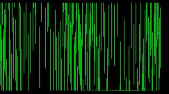
DSD/1 bit DS DAC
chip output:
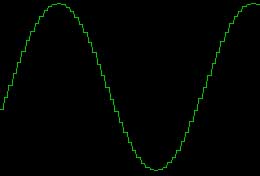
3 bit DS DAC
chip output:
R2R DAC
chip output:
images taken from
http://www.mother-of-tone.com/conversion.htm
But there are lots of NOS (Non Over Sampling) and 'filterless' DACs on the market that actually put out 'jagged' signals.
Here's a 'cheapy'
Archimago measured at the device output.
There are people that think all R2R outputs look like this but is not the case. Over Sampling makes the steps much smaller and 'errors' are moved higher above the audible range.
Add to that most headphones and speakers are so 'sluggish' they will 'smooth out' the jagged response and if the speakers/headphones don't do this for NOS 44.1kHz signals the ears will anyway.
There are even expensive DACs with similar actual output signals that are thought of highly in the subjective audiophool world.
Metrum Acoustics being one of them. Below the analog output signal of the 'Metrum Quad DAC'. (Picture from OJ-neg at
SBAF)
To confuse the non technical minded folks even more you often see these plots here and there:
This is taken from:
stereophile and shows 'jagged' (and noisy) squarewave outputs from a DS DAC chip.
Whaaaat ? Can DS chips also output (noisy) jagged signals. Yes, as that is (close to) the actual signal that it must produce at -90dB 16 bit.
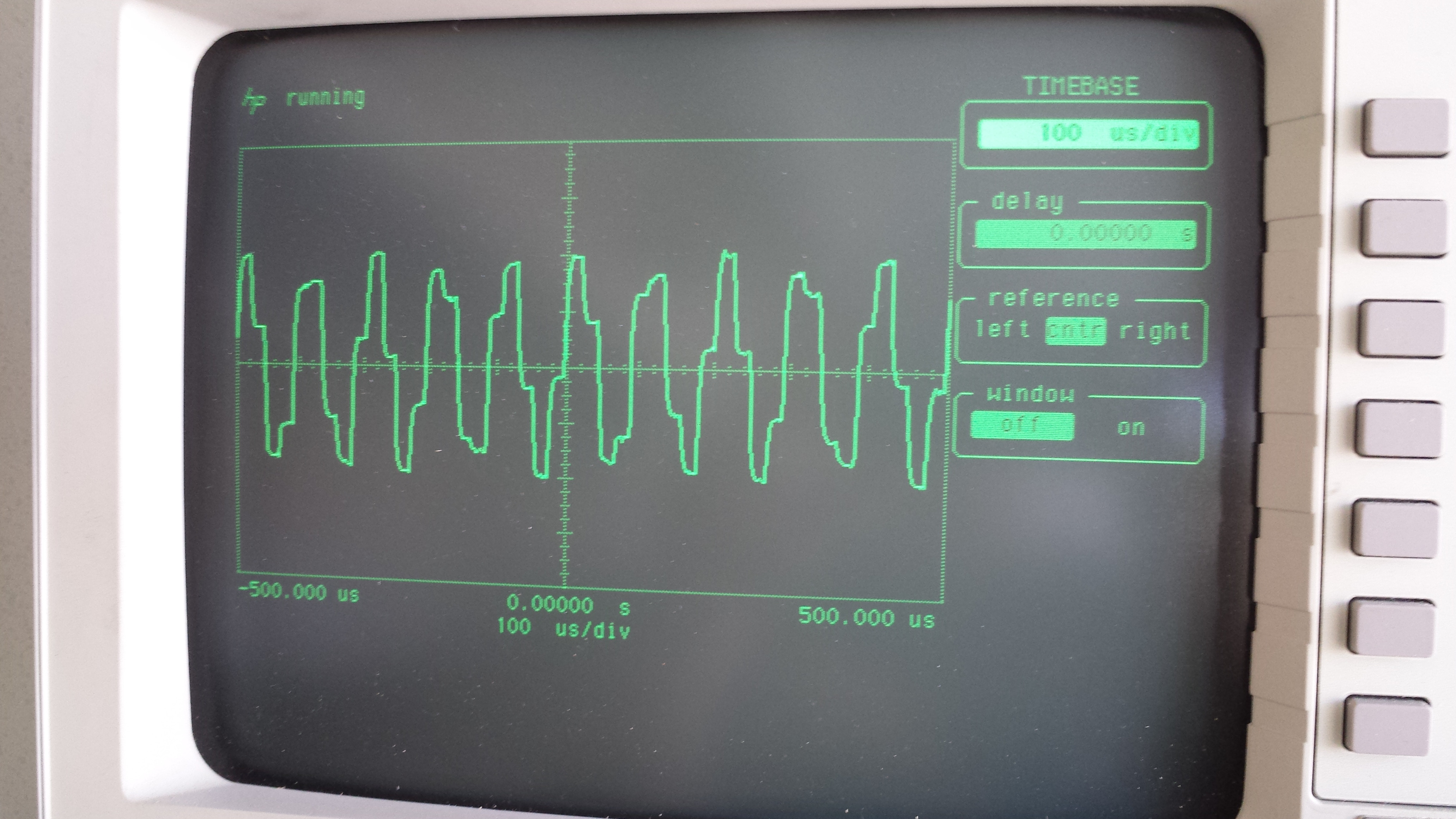
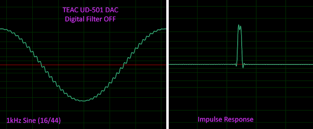
But the
UD501 for instance (measured by Archimago) in the (to me) wrong setting to use it in, being 'NOS setting' can also produce 'jagged' signals but produces very nice needle pulses and squarewaves which 'shows' how great the impulse response is and how wonderful it must sound... behold.
Of course these artificial signals do not exist in recorded music so don't have to be perfect. Sinewaves need to be 'perfect'.
Some manufacturers (and audiophools), however, keep insisting filterless NOS DAC's are THE best way to reproduce a digitized recording.
Comparing the actual 'analog' waveforms that were recorded to the actual reproduced analog waveforms will show how wrong their thinking is.
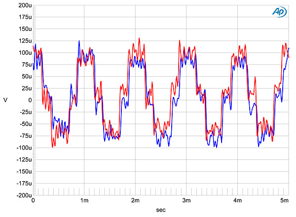
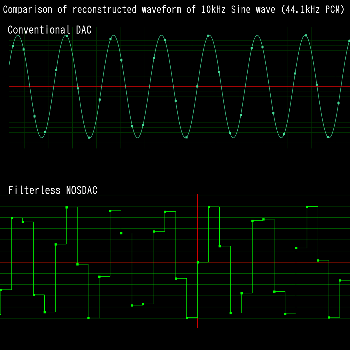
Below a picture taken from
Computeraudiophile and a bit 'misused' by me to make my point.
Consider the signal upper trace the 'original' recorded signal and the lower one from a NOS filterless ladder DAC.
The upper signal is also what one gets when looking at the output of any (properly reconstruction filtered) R2R (ladder) or DS DAC.
The lower trace is what the 'digital value representation' of the digital signal that is actually sent to the DAC chip looks like as well.
The upper trace is the waveform that is represented by the lower trace as it is supposed to come out of a properly constructed DAC device.
The problem with a lot of measurements is that most people are not technically proficient enough to understand what they are looking at and even more at what point in a circuit and what the audible consequences are.
Even for technical people some plots are still a mystery when scales don't come with it.
I am prepared to say that measurements are great and can say a LOT to those that understand it but are confusing and often give the wrong signals to those who do not understand what they are looking at. Often they start to draw their own (flawed or completely wrong) conclusions and vent their opinions all over the web.

")