• WANTED: Happy members who like to discuss audio and other topics related to our interest. Desire to learn and share knowledge of science required. There are many reviews of audio hardware and expert members to help answer your questions. Click here to have your audio equipment measured for free!

Modern Multi-Bit DAC vs Delta Sigma, specifically AKM's newest flagship, but also others

Ah, I understand a bit more now :)

But the point I'm trying to make is that this is advertised, not as a delta-sigma, but "premium switched resistor" DAC (title on datasheet).
It's not used as a 7 bit switched resistor DAC, and (IMO) if we're talking audio, 7 bit isn't premium
That's what happens when Marketing gets involved. The description uses "modulator" everywhere, so delta-sigma, but "switched resistor" (one way of implementing a conventional DAC) to describe the 7-bit DAC used by the modulator feeds into the anti-delta-sigma pro-R2R DAC crowd. The end result is not determined by the 7-bit DAC, but this way they can advertise "switched-resistor" and grab the audiophile DS-hating crowd whilst providing superb performance (from the delta-sigma architecture). The end DAC has about 23-bit performance based upon SNR.

Look at the picture in the article I linked and replace the 1-bit DAC with a 7-bit DAC, then add ~6*6 dB = 36 dB additional SNR from the multibit ADC inside the delta-sigma loop.

Marketing has provided some of the most convoluted descriptions of circuits that I have ever seen...
 
Last edited:
Aight, sorry for the accusation - one thing that sucks about written communication is that tone isn't easily conveyed
No worries :) As long as we all get smarter afterwards it’s all good. I’ll try to watch my manors.

In any case, the main confusion here is the separation between the digital part of the DAC: ak9141, and the analog part: ak4499EX.

As others have stated, this may have been done because of marketing reasons. Or possibly the chips are made from vastly different production processes, making it harder to pack them together.

Note that this chip combo is also current output vs voltage output of most of the other AK DACs. Clearly this combo uses some other technology vs the lower budget models, so it’s logical to position it differently as well.
 
That's what happens when Marketing gets involved. The description uses "modulator" everywhere, so delta-sigma, but "switched resistor" (one way of implementing a conventional DAC) to describe the 7-bit DAC used by the modulator feeds into the anti-delta-sigma pro-R2R DAC crowd. The end result is not determined by the 7-bit DAC, but this way they can advertise "switched-resistor" and grab the audiophile DS-hating crowd whilst providing superb performance (from the delta-sigma architecture).

Look at the picture in the article I linked and replace the 1-bit DAC with a 7-bit DAC, then add ~6*6 dB = 36 dB additional SNR from the multibit ADC inside the delta-sigma loop.

Marketing has provided some of the most convoluted descriptions of circuits that I have ever seen...
I'm not sure which picture you're referring to, but are you saying for every bit added to the DAC, SNR increases by 6dB?

Is this DAC from AKM (AK4499EX), its 7 bits are actual independent bits, right? Not cascaded?

I'm reading both threads at the moment and am going to try to understand what's in them and integrate this afternoon
 
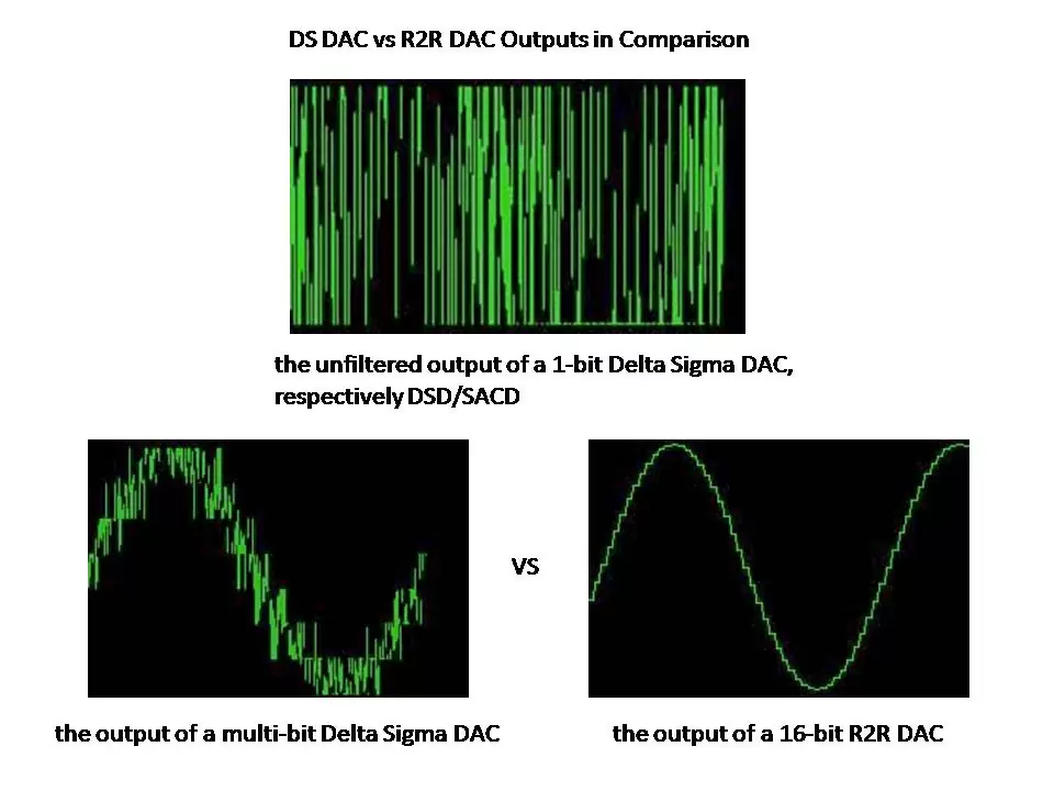
DSvsNOSR2R.jpg.webp
It should look something like the image on the lower left side.

Or this:
1709148303028.gif

See: https://www.eetimes.com/d-a-converter-enhances-sound-quality/

A horrible mess, isn’t it ;) It’s hard to believe this would yield much better final output than the much cleaner looking R2R output on the right.
 
Last edited:
is all marketing nonsense to justify the higher price one pays for 2 chips instead of just 1 that does the same.
There are rumors AKM have encountered difficulties with the original 1-chip AK4499 in that it did not reach initial performance goals. On-chip crosstalk is likely the problem. The chip is just a really complex beast, also making any updates to the design much more difficult.

That's why they were already thinking about a split-chip system... and then came the fire...

In the end, I'm pretty confident the split into a front-end + modulator and a fast precision 7-bit DAC was not a marketing idea exclusively.
 
I'm not sure which picture you're referring to, but are you saying for every bit added to the DAC, SNR increases by 6dB?

Is this DAC from AKM (AK4499EX), its 7 bits are actual independent bits, right? Not cascaded?

I'm reading both threads at the moment and am going to try to understand what's in them and integrate this afternoon
A deeper dive into delta-sigma designs is probably beyond ASR, or at least what I want to put into it right now... I do wish I had that second part of the delta-sigma article but oh well. The texts I linked provide a lot more detail.

The 7-bit DAC can be considered a piece of the bigger (overall) DAC. Replace a single-bit DAC inside the delta-sigma loop with a multi-bit DAC and you'll have a single stage multi-bit delta-sigma loop (modulator). You gain SNR from oversampling and filtering the modulator's output, and gain additional SNR due to the additional DAC bits inside the modulator. The complete DAC as seen from the outside world (the customer) only sees the result after the modulator and filters, so to them (and to any external measurement device) it is a 23-bit DAC.

Cascading would be taking that first picture in my article and duplicating the block. There are many schemes for cascaded architectures and they can get very complex. There are often connections, analog and digital, among stages to improve performance and keep the feedback loops stable. You are trading additional stages, additional internal bits, oversampling ratio, and stability to gain the performance desired.

A delta-sigma DAC includes a number of analog and digital parts, which can be separated into different chips. There can be many reasons for using multiple chips... The digital chip can use advanced process nodes (e.g. 5 nm to maybe 25 nm features) so it is smaller and requires less power while still providing a large amount of processing. But the smallest digital devices rarely have good analog performance, and low voltage breakdown leaves little headroom for analog signals. The analog chip likely uses a larger process node, e.g. 65 nm or even larger, that provides more voltage headroom and better analog performance. Separate chips also isolates the digital processing noise from the sensitive analog devices, and analog process nodes may include additional features (on-chip components) to support analog circuits.

HTH - Don
 
Last edited:
Sorry guys to chip in with a less (least...) technical aspect, I am just curious:

@mike7877 you said in the very first post that subjectively speaking when comparing all those different DACs (DX1, E30 II, E30II lite, E50, E70 Velvet) the Velvet was a totally different ball game

Can this be due to 'this combo uses some other technology vs the lower budget models' as @voodooless stated or due to some other reasons?
Is the higher cost justified? I mean does it sound really that much better? (I know all DACs shall sound the same but still I am curious)
Thank you
 
DSvsNOSR2R.jpg.webp
It should look something like the image on the lower left side.

Or this:
View attachment 353009
See: https://www.eetimes.com/d-a-converter-enhances-sound-quality/

A horrible mess, isn’t it ;) It’s hard to believe this would yield much better final output than the much cleaner looking R2R output on the right.
That is before the final anti-imaging and noise-rejection filters. You cannot draw conclusions from that, any more than you could draw conclusions from looking at the raw unfiltered output of the modulator, or the output of a class-D amplifier before the output filter.

Edit: @KSTR was faster on the keyboard...
 
It's an interesting topic and that AKM chip you mention is very intriguing! There are also multiple kinds of R2R DACs: The main two that I am aware of being the usual segmented and sign-magnitude.

Example of segmented string are chips from Analog Devices such as AD1865 and AD1868 which use the (partially) segmented design:

The DACs on the AD1865 chip employ a partially segmented
architecture. The first four MSBs of each DAC are segmented
into 15 elements. The 14 LSBs are produced using standard R-2R
techniques. Segment and R-2R resistors are laser trimmed to pro-
vide extremely low total harmonic distortion. This architecture
minimizes errors at major code transitions resulting in low out-
put glitch and eliminating the need for an external deglitcher

Example of sign-magnitude are the famous Burr-Brown PCM1704 or PCM63:

SIGN-MAGNITUDE ARCHITECTURE
Digital audio systems have traditionally used laser-trimmed,
current-source DACs in order to achieve sufficient accuracy.
However, even the best of these suffer from potential low-
level nonlinearity due to errors in the major carry bipolar
zero transition. Current systems have turned to oversampling
data converters, such as the popular delta-sigma architec-
tures, to correct the linearity problems. This is done, how-
ever, at the expense of signal-to-noise performance, and the
noise shaping techniques utilized by these converters creates
a considerable amount of out-of-band noise. If the outputs
are not properly filtered, dynamic performance of the overall
system will be adversely effected.

The PCM1704 employs an innovative architecture which
combines the advantages of traditional DACs (e.g., excellent
full-scale performance, high signal-to-noise ratio, and ease
of use) with superior low-level performance. This architec-
ture is referred to as sign-magnitude. Two DACs are com-
bined in a complementary arrangement to produce an ex-
tremely linear output. The two DACs share a common
reference, and a common R-2R ladder for bit current sources.
The R-2R ladder utilizes dual balanced current segments to
ensure ideal tracking under all conditions. By interleaving
the individual bits of each DAC and employing precision
laser-trimming of resistors, a highly accurate match between
the two DACs is achieved.

The sign-magnitude architecture, which steps away from
zero with small steps in both directions, avoids any glitching
or large linearity errors, and provides an absolute current
output. The low-level performance of the PCM1704 is such
that true 24-bit resolution can be realized around the critical
bipolar zero point.
 
sevenSo this is a 7 bit multi-bit DAC being used in DS mode?

How many bits are AKMs DS DACs then, like the 4493S?
No, DS is not directly involved here, it's not a mode of the chip, but the companion chip provides a 7-bit output from a multibit Delta-Sigma modulator.

It's a very fast precision 7-bit parallel DAC with banks of 2^7 = 128 equal switched resistors, conversion directly takes place in one single clock cycle. Those resistors which are 'on' for a given cycle are randomly selected by a clever algorithm so that any small tolerances don't generate harmonic distortion but are converted to a very low-level random noise (similar algorithms are also present in pretty much any other high-quality DS DAC).

4490/93 are different in that the final output DAC is less bits (5 or 6) and it switches capacitors, not resistors. They are also different in many other fine details.
 
It's an interesting topic and that AKM chip you mention is very intriguing! There are also multiple kinds of R2R DACs: The main two that I am aware of being the usual segmented and sign-magnitude.

Example of segmented string are chips from Analog Devices such as AD1865 and AD1868 which use the (partially) segmented design:

The DACs on the AD1865 chip employ a partially segmented
architecture. The first four MSBs of each DAC are segmented
into 15 elements. The 14 LSBs are produced using standard R-2R
techniques. Segment and R-2R resistors are laser trimmed to pro-
vide extremely low total harmonic distortion. This architecture
minimizes errors at major code transitions resulting in low out-
put glitch and eliminating the need for an external deglitcher

Example of sign-magnitude are the famous Burr-Brown PCM1704 or PCM63:

SIGN-MAGNITUDE ARCHITECTURE
Digital audio systems have traditionally used laser-trimmed,
current-source DACs in order to achieve sufficient accuracy.
However, even the best of these suffer from potential low-
level nonlinearity due to errors in the major carry bipolar
zero transition. Current systems have turned to oversampling
data converters, such as the popular delta-sigma architec-
tures, to correct the linearity problems. This is done, how-
ever, at the expense of signal-to-noise performance, and the
noise shaping techniques utilized by these converters creates
a considerable amount of out-of-band noise. If the outputs
are not properly filtered, dynamic performance of the overall
system will be adversely effected.

The PCM1704 employs an innovative architecture which
combines the advantages of traditional DACs (e.g., excellent
full-scale performance, high signal-to-noise ratio, and ease
of use) with superior low-level performance. This architec-
ture is referred to as sign-magnitude. Two DACs are com-
bined in a complementary arrangement to produce an ex-
tremely linear output. The two DACs share a common
reference, and a common R-2R ladder for bit current sources.
The R-2R ladder utilizes dual balanced current segments to
ensure ideal tracking under all conditions. By interleaving
the individual bits of each DAC and employing precision
laser-trimming of resistors, a highly accurate match between
the two DACs is achieved.

The sign-magnitude architecture, which steps away from
zero with small steps in both directions, avoids any glitching
or large linearity errors, and provides an absolute current
output. The low-level performance of the PCM1704 is such
that true 24-bit resolution can be realized around the critical
bipolar zero point.
And a few others... Plus the choice of voltage cells or current cells.
 
Guys, it’s not about conclusions, it’s just to visually show what type of signal comes output these things. Obviously it needs further filtering…
OK, for illustration of how much HF attenuation will be needed a plot of the unfiltered output has some use.
 
Because you’re looking at the wrong datasheet. The AK4191 does the modulation bits. It can do direct DSD. Which is rather silly if you have a 7-level DAC on hand… why not actually take advantage?

It is not 7-level. It is 7-bit. And it is two-complement, so you have values 0 to 63 and also 0 to -63. This means that the 4499EX probably has 63 resistors and two opposite sources of potential, and the resistors to switch among the 63 are always picked sort-of-randomly.
 
It is not 7-level. It is 7-bit. And it is two-complement, so you have values 0 to 63 and also 0 to -63. This means that the 4499EX probably has 63 resistors and two opposite sources of potential, and the resistors to switch among the 63 are always picked sort-of-randomly.
So how does that work? Clearly the AK4191 generates multibit PWM data, not PCM. The modulator is there, not in the AK4499EX.
 
So how does that work? Clearly the AK4191 generates multibit PWM data, not PCM. The modulator is there, not in the AK4499EX.

It is multi-level, but the levels are 127. The AK4499EX just realises them. It is not exactly PCM in the same way 1-bit DSD is not PCM.
 
It is multi-level, but the levels are 127. The AK4499EX just realises them. It is not exactly PCM in the same way 1-bit DSD is not PCM.
For multibit DS, you’ll need more than on level to be “on” at a time. You can’t do that with 127 levels and 7-bits.
 
Back
Top Bottom