- Joined
- Feb 23, 2016
- Messages
- 23,571
- Likes
- 44,337
A couple of clarifications.
Aliasing is when content above the Nyquist frequency (half the sampling rate) is folded back down into the recording by an ADC.
Imaging is when content below the Nyquist frequency shows up mirror imaged above the Nyquist frequency during playback by a DAC.
So what effect does upsampling have on these if any?
Using a Topping D10 balanced I played wideband white noise at a 384 khz sample rate into an RME Babyface Pro FS ADC at 48 khz. The noise was flat to at least 80 khz and likely well past 100 khz.
So next I played the 48 khz recording into the ADC capturing the result at 192 khz so we can see what is going on. I repeated this by upsamling that same file to 384 khz and playing it back.
A 132k FFT covering 96 khz. Red is the 48 khz file played at its native 48 khz, and Blue is the upsampling of the same file. Upsampling used a sharper filter with a quicker cut-off of the above Nyquist frequencies.

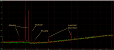
Next I created a file with a high level tone at 20 khz and one 10 db lower at 25.5 khz. The file was 384 khz sample rate and recorded by the ADC at 48 khz. The graph is of this file played back at its native 48 khz in Red and Green is the noise floor of the ADC.
You see the 25.5 khz tone aliasing back down to 22.5 khz. 25,500 hz is 1500 hz above 24,000 Nyquist frequency and gets reflected down to 22,500 hz as an alias. Note the aliased tone is only about 15 db lower than its original level. A sharper filter would have reduced this more or eliminated it. There is also a small amount of IMD distortion from the 20 khz and 25.5 khz tone showing up at 14.5 khz. There is some imaging of the 20 khz tone reflected upward to 28 khz. Then you see the 2nd and 3rd harmonic from simple analog distortion of the analog output stage. Plus some leakage of the 25.5 khz tone which was not filtered out. The IMD and Aliasing are now baked into the recording and no post filtering or upsampling will remove them.

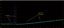
Next I upsampled the same file to 384 khz. Upsampled signal in Blue and green is the ADC noise floor. You still see the Aliasing and IMD as it has been recorded into the file and no post filtering or upsampling will remove it. Upsampling with Sox via Audacity did filter above Nyquist more steeply as already shown by the white noise profiles. As a result the leakage of the 25.5 khz tone is gone. The imaging of the 20 khz tone above Nyquist is gone as well. Harmonic distortion remains as that is an analog by product of the output stage.

Aliasing is when content above the Nyquist frequency (half the sampling rate) is folded back down into the recording by an ADC.
Imaging is when content below the Nyquist frequency shows up mirror imaged above the Nyquist frequency during playback by a DAC.
So what effect does upsampling have on these if any?
Using a Topping D10 balanced I played wideband white noise at a 384 khz sample rate into an RME Babyface Pro FS ADC at 48 khz. The noise was flat to at least 80 khz and likely well past 100 khz.
So next I played the 48 khz recording into the ADC capturing the result at 192 khz so we can see what is going on. I repeated this by upsamling that same file to 384 khz and playing it back.
A 132k FFT covering 96 khz. Red is the 48 khz file played at its native 48 khz, and Blue is the upsampling of the same file. Upsampling used a sharper filter with a quicker cut-off of the above Nyquist frequencies.
Next I created a file with a high level tone at 20 khz and one 10 db lower at 25.5 khz. The file was 384 khz sample rate and recorded by the ADC at 48 khz. The graph is of this file played back at its native 48 khz in Red and Green is the noise floor of the ADC.
You see the 25.5 khz tone aliasing back down to 22.5 khz. 25,500 hz is 1500 hz above 24,000 Nyquist frequency and gets reflected down to 22,500 hz as an alias. Note the aliased tone is only about 15 db lower than its original level. A sharper filter would have reduced this more or eliminated it. There is also a small amount of IMD distortion from the 20 khz and 25.5 khz tone showing up at 14.5 khz. There is some imaging of the 20 khz tone reflected upward to 28 khz. Then you see the 2nd and 3rd harmonic from simple analog distortion of the analog output stage. Plus some leakage of the 25.5 khz tone which was not filtered out. The IMD and Aliasing are now baked into the recording and no post filtering or upsampling will remove them.
Next I upsampled the same file to 384 khz. Upsampled signal in Blue and green is the ADC noise floor. You still see the Aliasing and IMD as it has been recorded into the file and no post filtering or upsampling will remove it. Upsampling with Sox via Audacity did filter above Nyquist more steeply as already shown by the white noise profiles. As a result the leakage of the 25.5 khz tone is gone. The imaging of the 20 khz tone above Nyquist is gone as well. Harmonic distortion remains as that is an analog by product of the output stage.
Attachments
Last edited:
