As some of you are aware, have been playing around with my Purifi SPK parts and working to determine a final configuration for them. As I have been trying various vented alignments, reminded me that I planned to share some useful observations about speaker impedance measures. I am multitasking projects but Covid just put a damper on going out in public here and thought I would start the thread.
A couple of quick caveats before I start:

Here is my measurement in comparison...

So why do they not match exactly? As I said earlier, conditions matter. Note that I used the Purifi SPK4 as a baseline. My SPK does not have the same damping and has the crossover mounted internally rather than externally. More importantly, I can say the build is essentially valid as the key peaks and valley frequencies match. The key ones being the leftmost peak (port resonant frequency), the next dip (box tuning frequency) and the next peak (driver resonant frequency). The other key inflections also match at 800 Hz, 2000 Hz and 8000 Hz. These indicate a good match of the tweeter and its crossover to the baseline.
Note the impedance magnitude difference is most likely due to my cabinet being a bit leakier than the reference Purifi one. I anticipate I will be able to reduce the box issues in upcoming steps. Also, as will examine later, there is a slight blip in the trace around 240 Hz. As Amir will often point out in his reviews, this indicates a (undesirable) resonance.
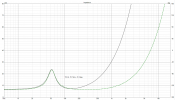
For simplicity, want to start a new baseline and offer the first major change by taking the same speaker and sealing the vent closed. If I did not have a published baseline for comparison, this is my next best way to establish one. I then could use a speaker modeling program to verify whether my baseline was a good one. Bear in mind, that that design model would need to include the crossover. If the crossover design is not known, could bypass and measure each driver independently in the cabinet and model without it.

While this a larger sealed box than would be suggested for this woofer, for the sake of this experiment, it shows what you would expect. Due to the woofer seeing greater push back as it tries to move against the trapped air, the box resonance frequency is now much higher and so is the impedance peak.
A couple of quick caveats before I start:
- While most of what I will present will be generally applicable, will the using the SPK parts to demonstrate some things and so may not be always be applicable to other speakers. The SPK woofer is a 4 ohm, lower Q woofer and the tweeter is a Mundorf AMT with a very flat 4 ohm impedance. The crossover is pretty typical but nothing that would prevent me from using it for this thread.
- Some of what I will show may be hard to apply without a baseline for comparison and frankly experience in speaker design. Am hoping to help members better understand some aspects of the impedances shown in Amir's reviews. That said, conditions matter. This includes the measurement voltage. software, environment and condition of the speaker being tested. In my case, my measurements are being done are at room temperature, using REW with a 100 ohm sense resistor using a Sound Blaster Audigy card to drive the speaker at 100 mV.
Here is my measurement in comparison...
So why do they not match exactly? As I said earlier, conditions matter. Note that I used the Purifi SPK4 as a baseline. My SPK does not have the same damping and has the crossover mounted internally rather than externally. More importantly, I can say the build is essentially valid as the key peaks and valley frequencies match. The key ones being the leftmost peak (port resonant frequency), the next dip (box tuning frequency) and the next peak (driver resonant frequency). The other key inflections also match at 800 Hz, 2000 Hz and 8000 Hz. These indicate a good match of the tweeter and its crossover to the baseline.
Note the impedance magnitude difference is most likely due to my cabinet being a bit leakier than the reference Purifi one. I anticipate I will be able to reduce the box issues in upcoming steps. Also, as will examine later, there is a slight blip in the trace around 240 Hz. As Amir will often point out in his reviews, this indicates a (undesirable) resonance.
For simplicity, want to start a new baseline and offer the first major change by taking the same speaker and sealing the vent closed. If I did not have a published baseline for comparison, this is my next best way to establish one. I then could use a speaker modeling program to verify whether my baseline was a good one. Bear in mind, that that design model would need to include the crossover. If the crossover design is not known, could bypass and measure each driver independently in the cabinet and model without it.
While this a larger sealed box than would be suggested for this woofer, for the sake of this experiment, it shows what you would expect. Due to the woofer seeing greater push back as it tries to move against the trapped air, the box resonance frequency is now much higher and so is the impedance peak.
Last edited:
")